Finally after a long search for drawings and information of the Liebherr LR 1750, Wouter and I started drawing the crane in September 2011. The intention is to build the crane in scale 1: 14.5 and to make it fully functional, so that it can be operated by radio.
The aim is to be able to approximate the lifting table to scale, for this the crane would have to be equipped with more than 200 kg of ballast (crane ballast and superlift ballast together). I hope that we can complete the drawing work in one year, as soon as the weight of the various parts is known, we can determine the force on the undercarriage and calculate the delays and engines. The biggest challenge will be getting rid of the drive in the tracks.
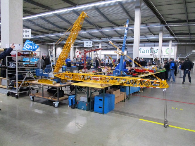
The reason for building the crane in scale 1: 14.5 has to do with the scale of the vehicles of other members within our modeling club. In the near future I hope to be able to persuade a number of members to build semi low-loaders in order to get the various crane parts transported on the MBVP model construction track. can unload and assemble trucks.
Our LTM 1400's will also be operational by then so that we can unload the parts from the trucks and assemble the crawler crane.
In the meantime I have been able to take a lot of pictures myself, but I have also received many from other crane enthusiasts.
But if there are still people who have detailed photos of an LR 1750 or LG 1750, I would be more than happy to recommend any help, especially parts during transport.
The tricky part is that the cranes are very often on a refinery, so you cannot get close or that photography is not allowed. And because they are relatively expensive cranes, they never stay in the same place for long, you often get information too late where a crane is being built or a lifting job is being done.
Technical details:
Dimensions of the scale model
Dimensions of the real crane
Length tracks
820mm
11.900mm
Width crane
710mm
10.300mm
Central ballast
max. 31kg
Max. 95 ton
Counterweight superstructure
max. 80kg
max. 245 ton
Superlift ballast
max. 131kg
max. 400 ton
Length S-boom
max. 6517mm
max. 94.5 mtr.
Length D-boom
2172mm
31.5 mtr.
Length fly jib
max. 7241mm
max. 105 mtr.
Weight of the crane
+/-400kg
+/- 1.175.000 kg
I regularly post updates with more information and pictures of the project on the Bouwmachineforum.
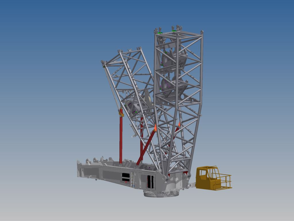
The drawing work for the S-boom is almost completed, the D-boom still has to draw the main piece. I am now working on the final drawing on the jib, which I would like to have completed before the end of January. Then I start drawing on both sprinkles.
600 Tons Top section
Jib pivot section
S-boom
Derrick boom
S-boom pivot section
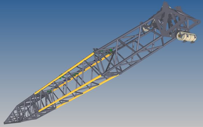
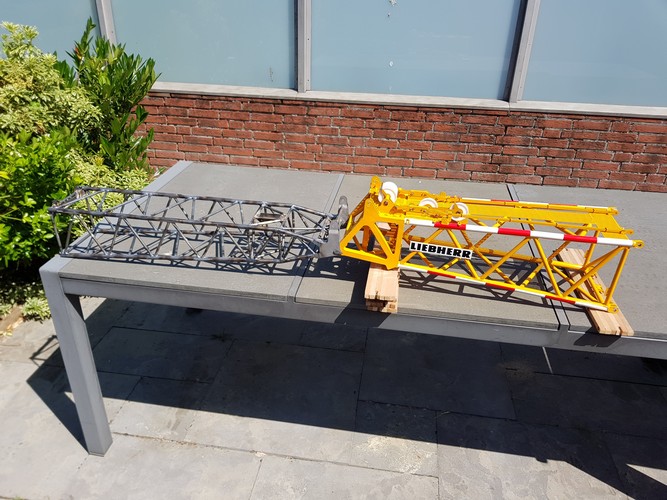
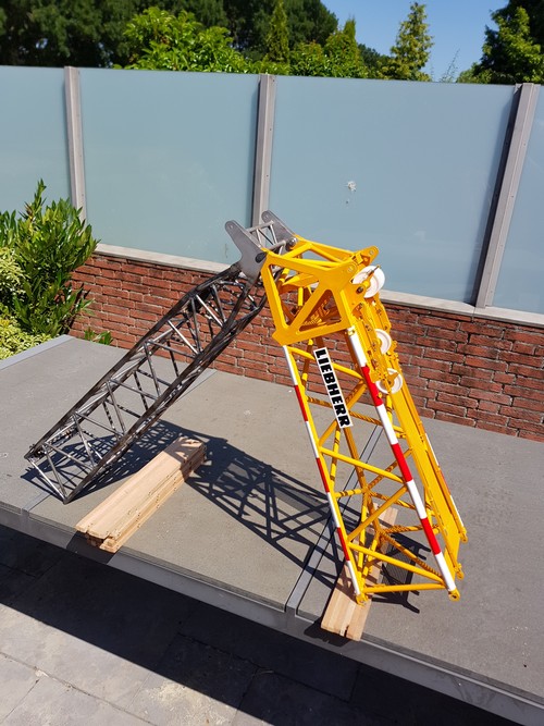
Top S-boom with sprenkels and Jib pivot section
August 2012:
Almost the entire boom has now been drawn, except for one 3-meter section, the main boom is complete. The photo also shows the full jib. The real boom without a 3-meter piece is 91 meters, converted to 6,275 meters. According to the calculations, the weight of the boom sections with the chosen materials also comes out to scale.
The jib is actually 105 meters long, and that is 7,241 meters to scale. This results in a tip height of 13,516 meters to scale.
Pivot section D-boom
Top section D-boom
Breidel D-boom
January 2013:
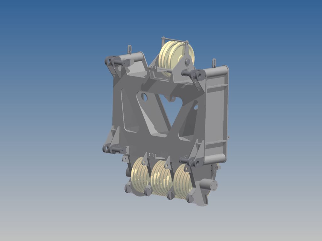
600 Tons hook
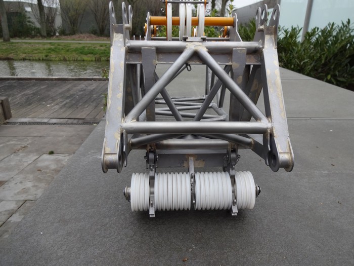
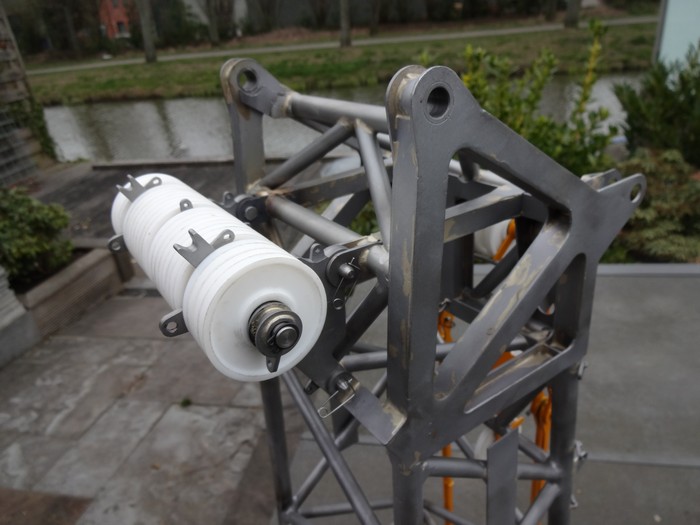
Front view 400 tons Top-section
Rear view 400 tons Top-section
April 2013:
construction of the 600 tonne hook
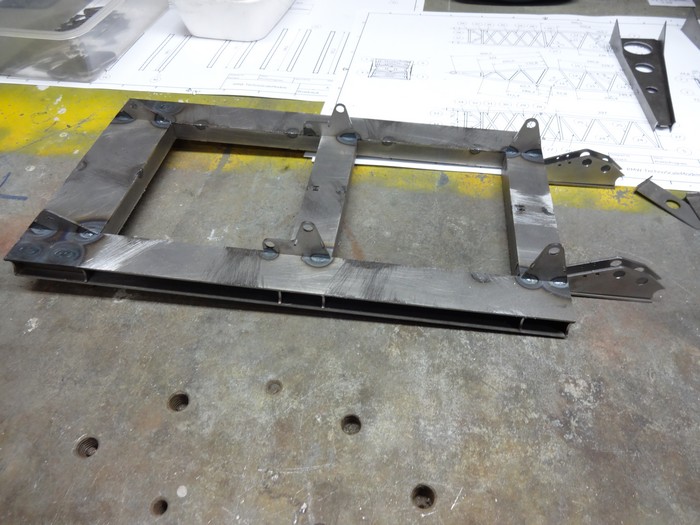
Design of the ballast platform
Ballast platforms
Details added on Superstructure
September 2013:
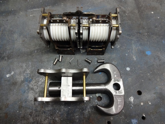
Manufacture lifting hook
600 tons hook
December 2013:
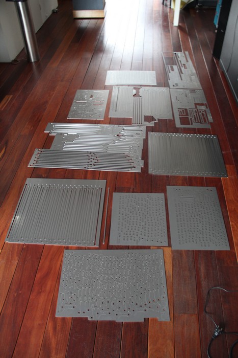
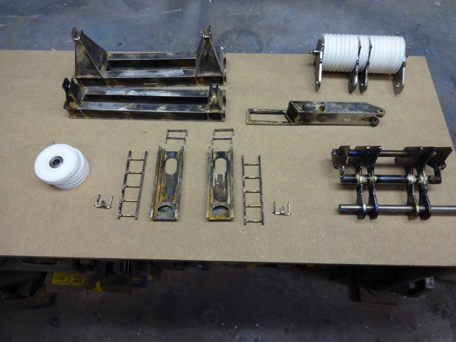
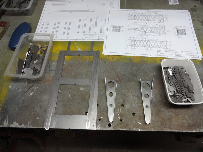
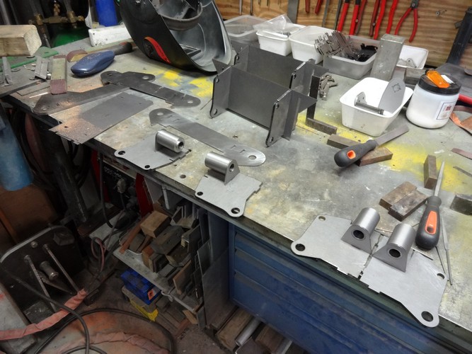
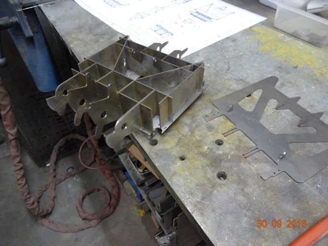
At the beginning of December I placed the order for the laser cutting of the first parts for the superstructure. During the Christmas holidays I started putting together the first parts.
Overview of laser cutting Phase 1
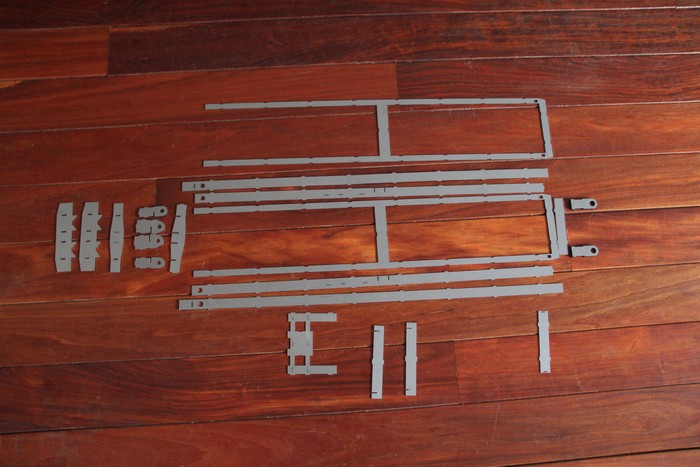
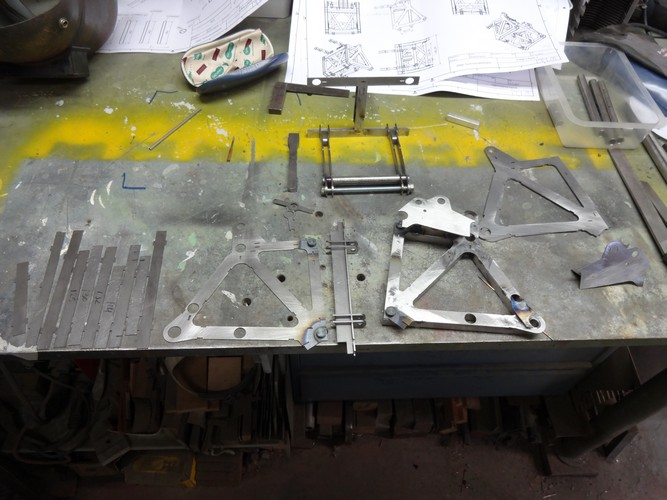
Parts A-frame
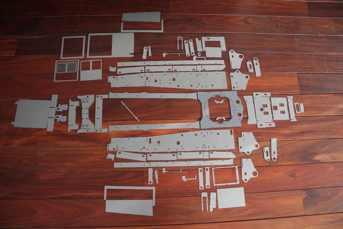
Parts Superstructure
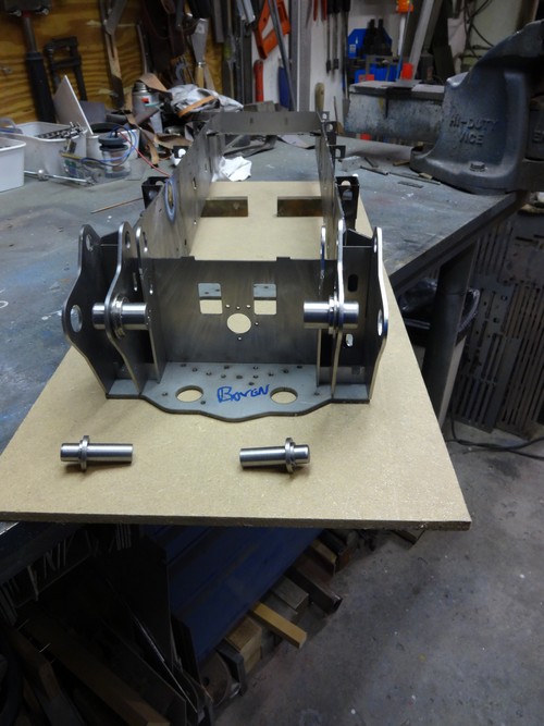
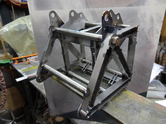
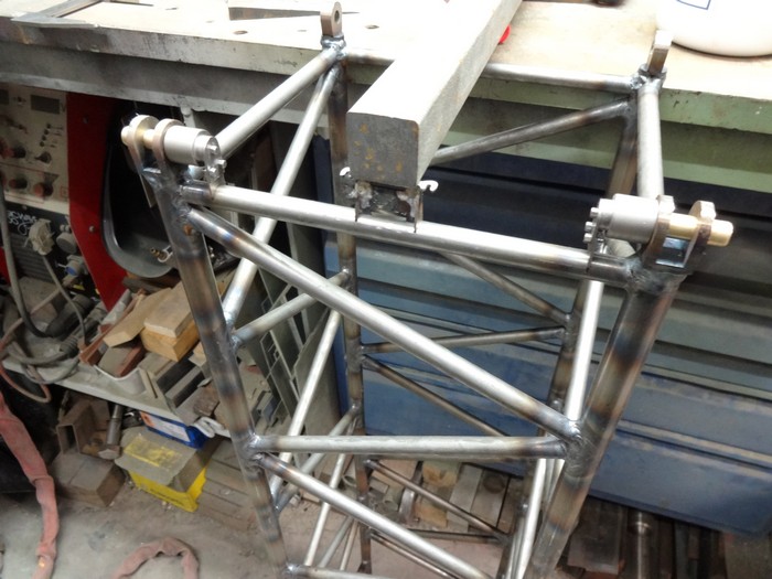
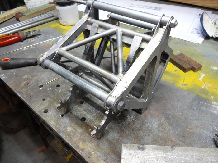
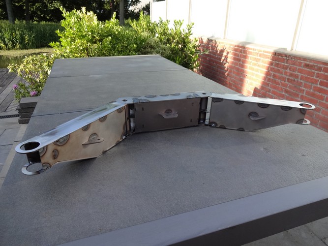
Start building the A-frame
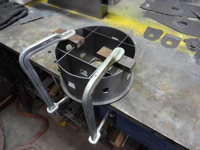
Assemble sheave block / Breidel part B
First parts ready
Preparation S-boom parts
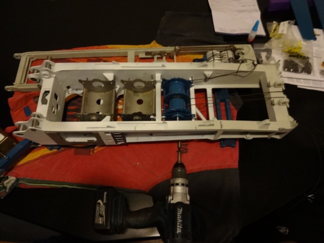
Compose Superstructure
March 2014:
Sheave block / Breidel part A + B ready
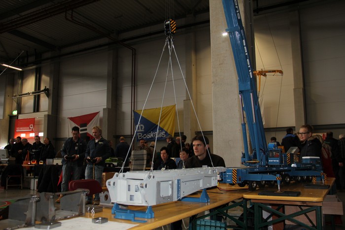
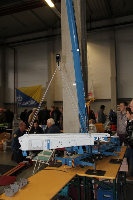
Superstructure in the hook during Modelshow Europe in Ede
April 2014:
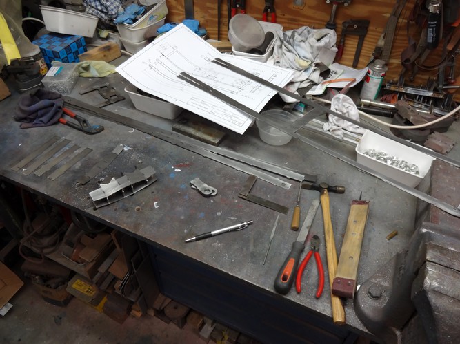
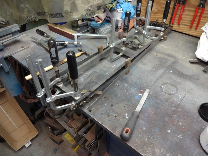
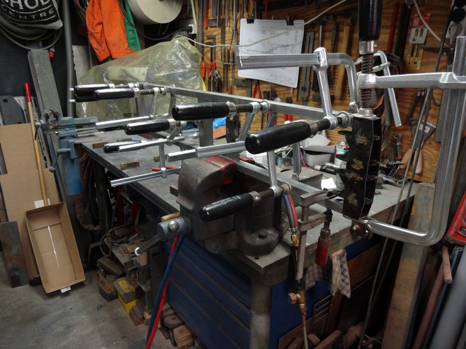
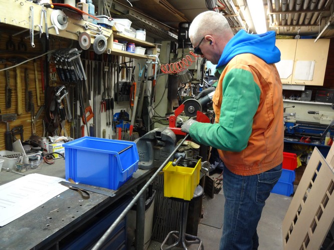
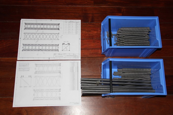
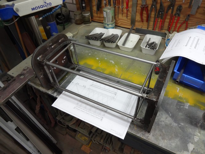
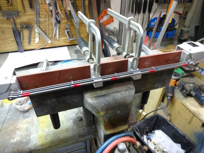
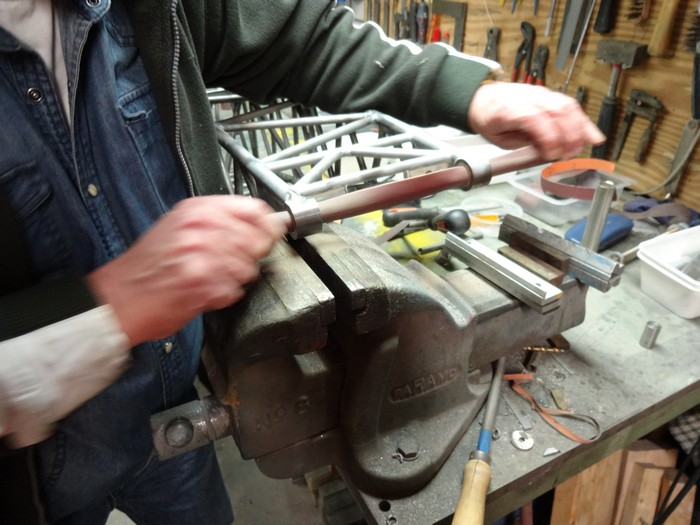
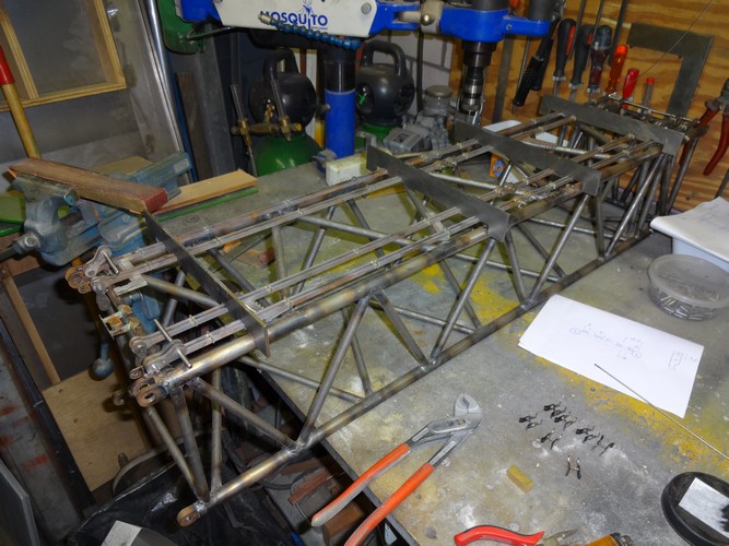
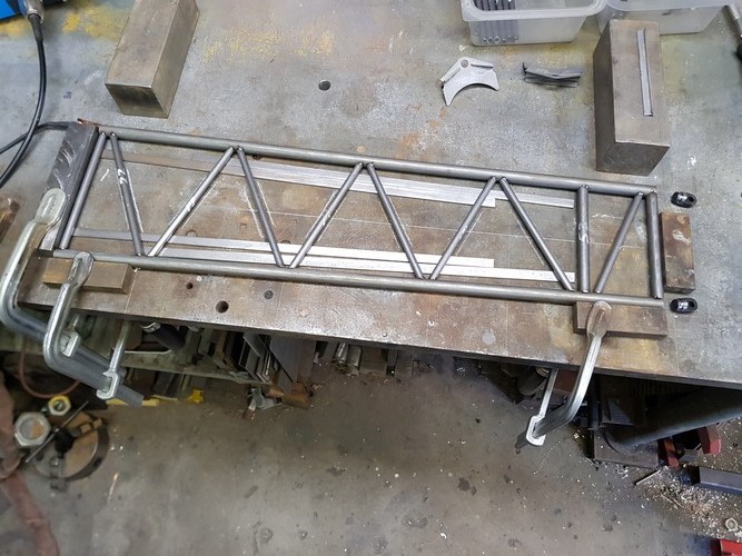
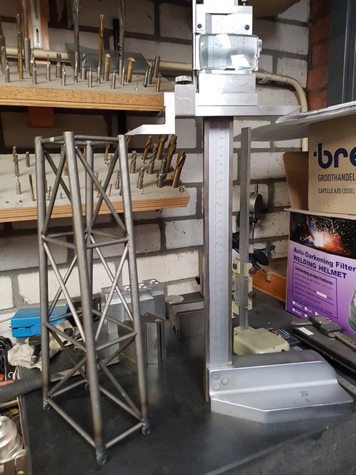
Start manufacturing S-boom, Turn main girders to length
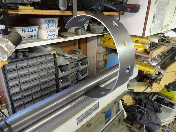
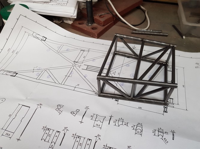
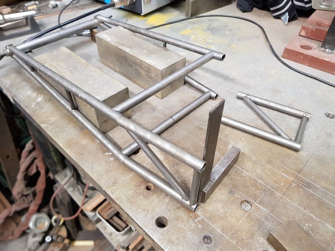
Making a construction template for the boom parts
Mill radius on diagonals
Rev0 template with connectors
Template rev1 without connectors
May 2014:
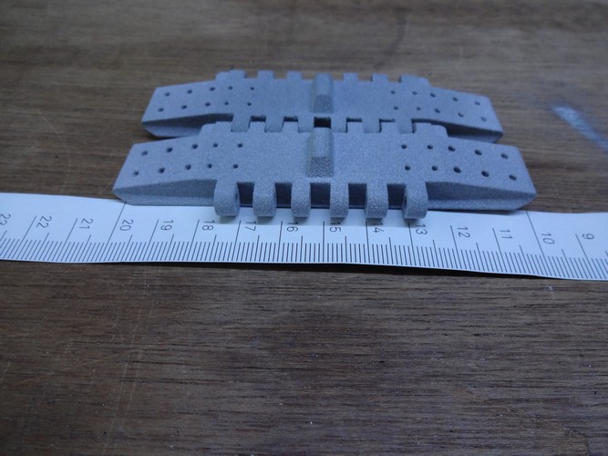
Have 2 plastic track shoes printed at Shapeways
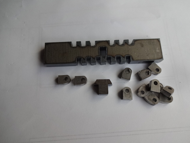
Laser cutting a set of steel track shoes and loose pivot points as a test
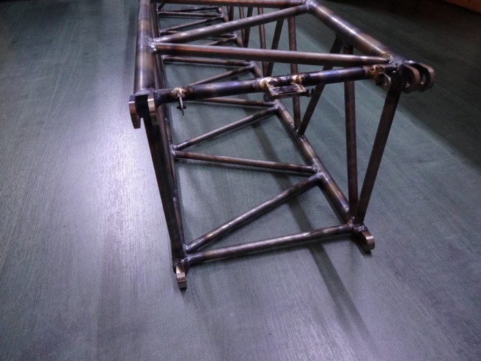
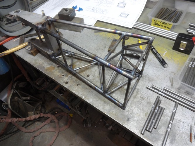
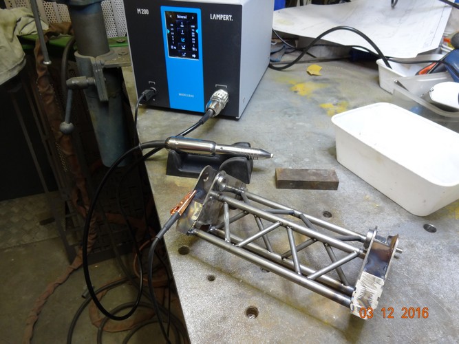
June 2014:
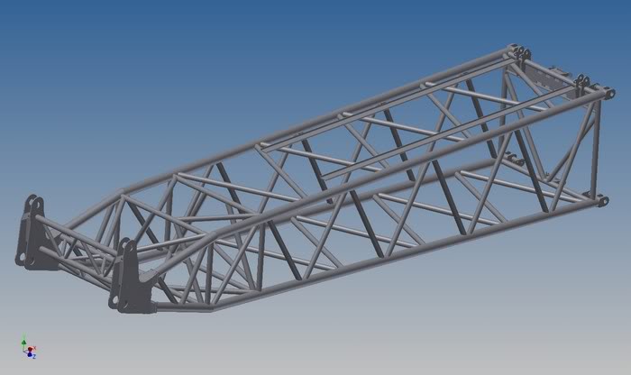
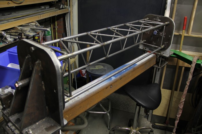
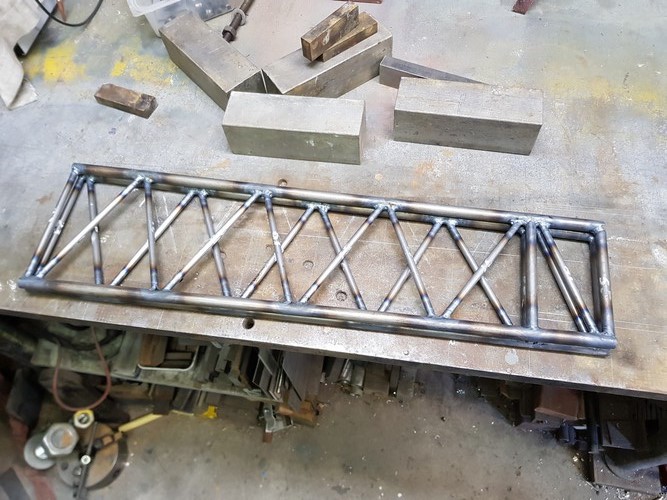
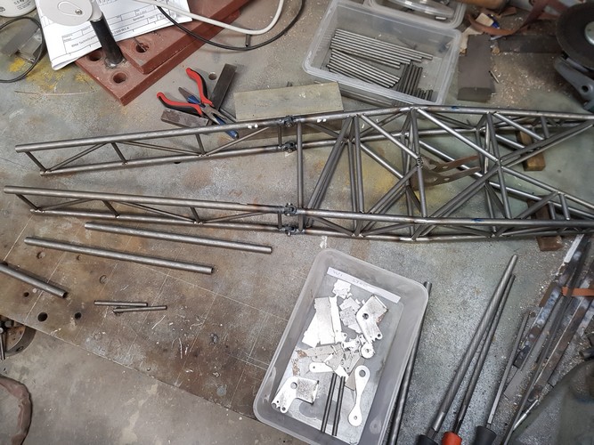
S-boom 14 mtr. Intermidiate section
S-boom Top-section 600 ton
Straightening of the boom parts after welding
September 2014:
Straightening of the boom sections after welding
November 2014:
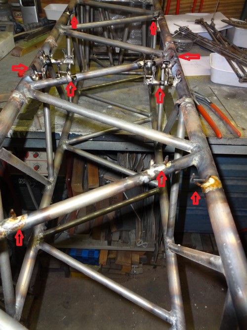
Welding of the couplings in the new template
Applying details
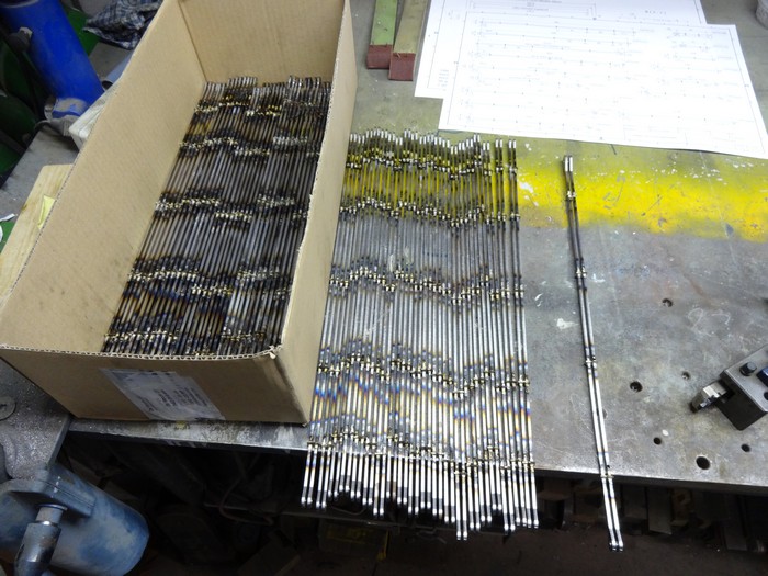
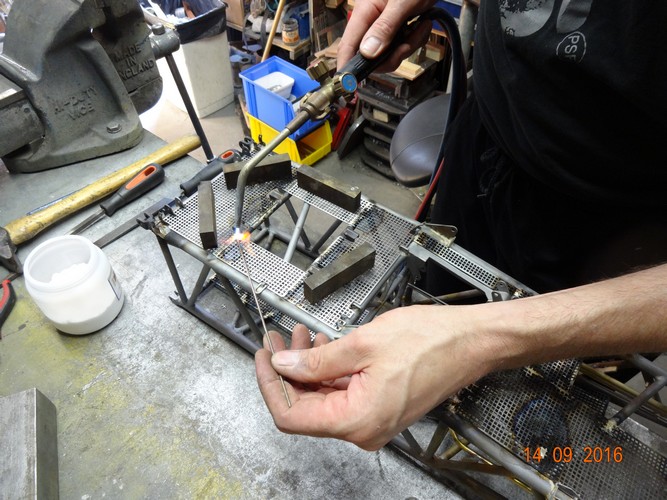
December 2014:
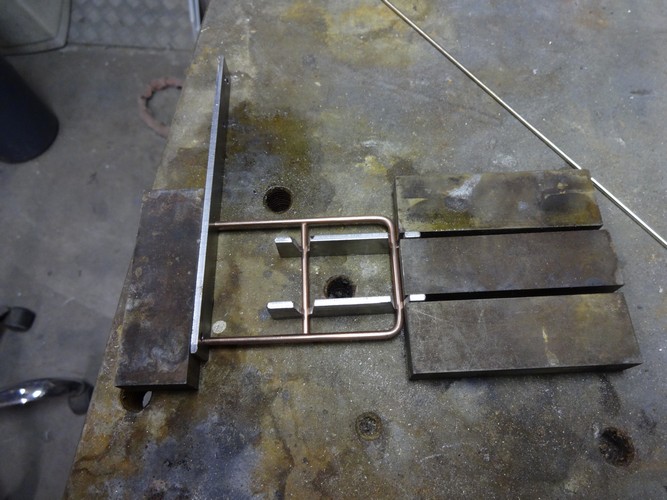
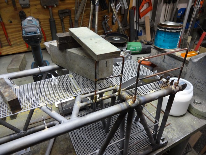
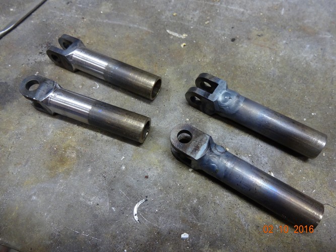
Assembling the tie rods
Brazing the tie rods
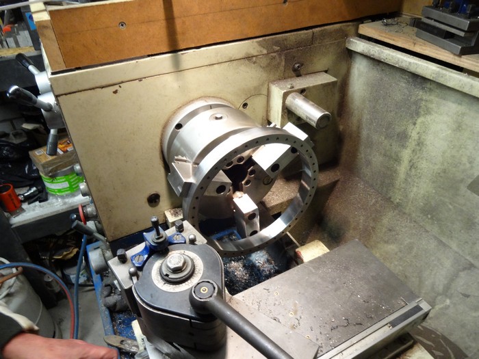
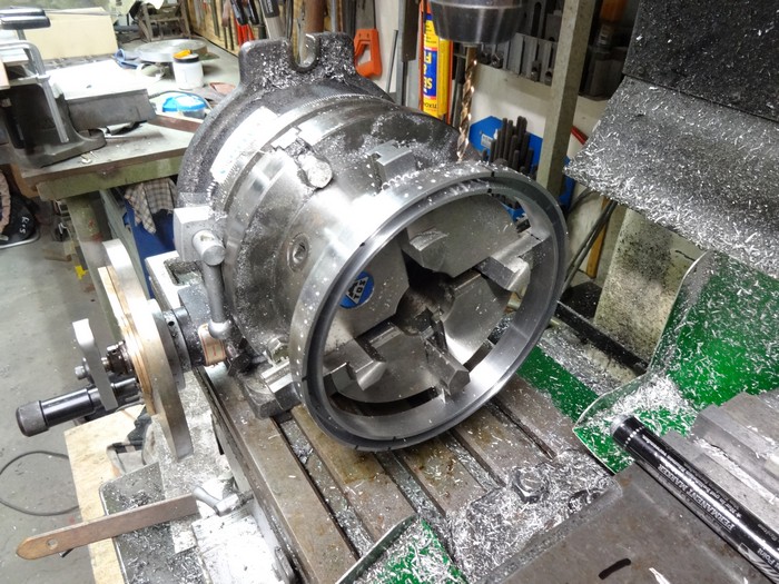
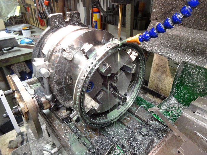
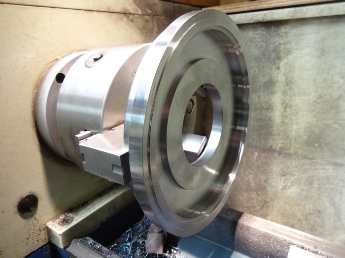
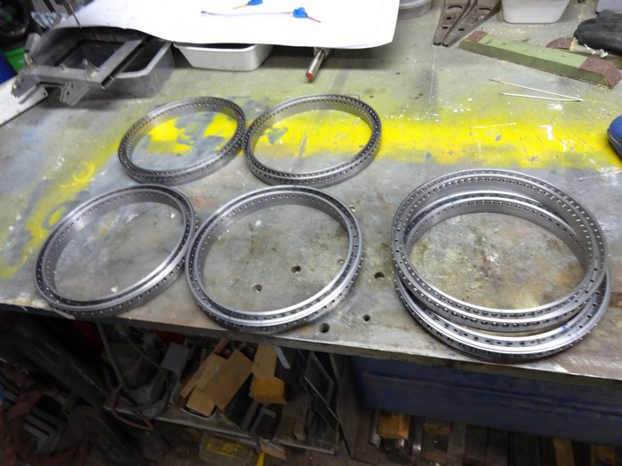
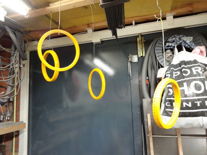
Production of slewing rings continues
Drilling holes in the outline of the Quick connector Base ring
Reaming the holes
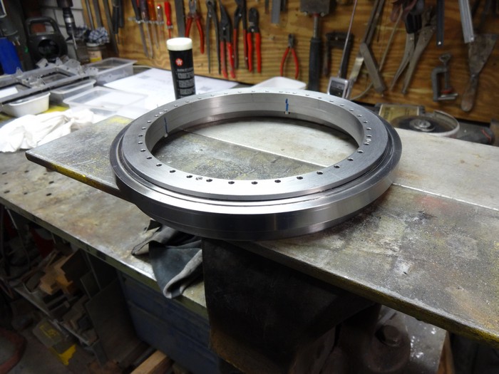
Making a special plate to be able to clamp rings tension-free
Ring clamped around special plate
Base-ring quick connector ready
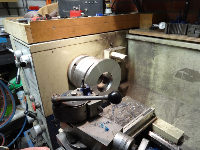
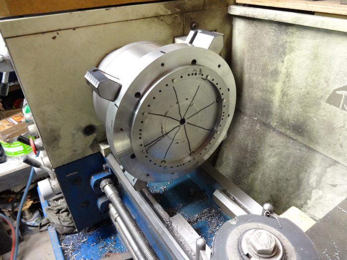
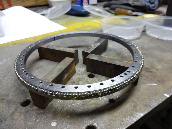
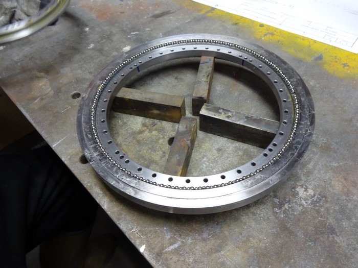
Installing balls for trail fit of the slewing ring
Slewing ring trial assembled and tested with 200 kg axial load
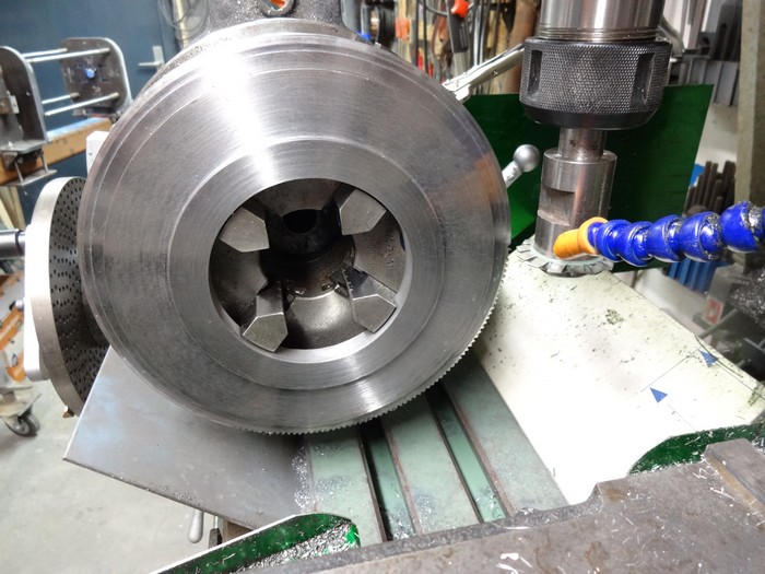
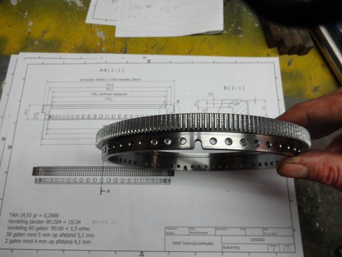
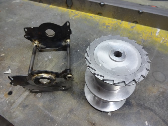
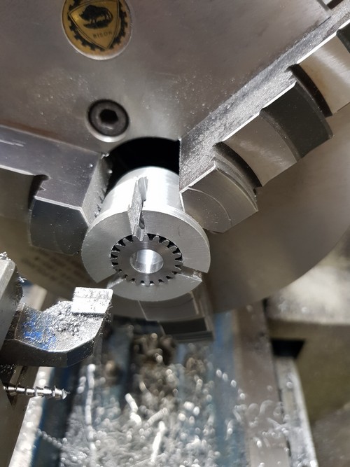
Milling Module 1 teeth on the outer ring
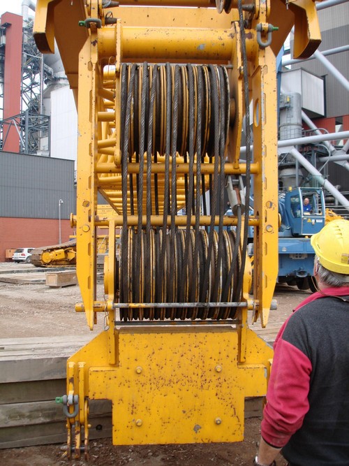
Reaming out the holes for the quick connector on the bearing ring
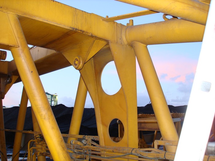
The quick connector of the real slewing ring
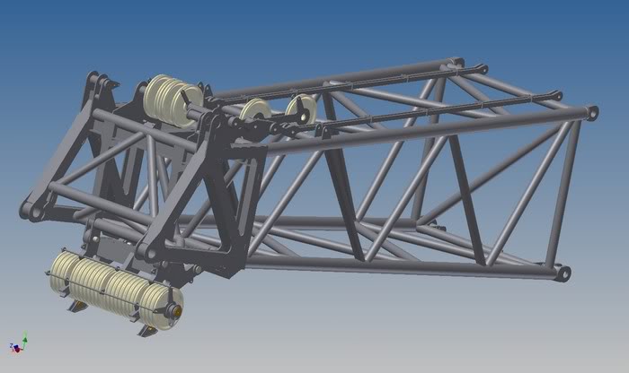
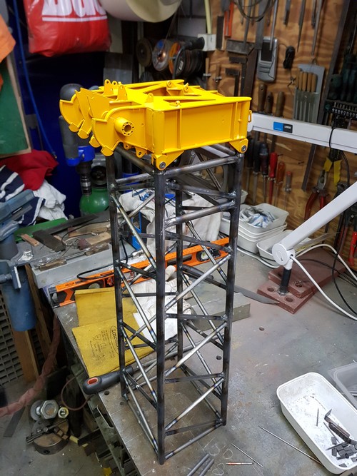
Continued assembly of the 600 ton top section
Assembly of the 600 ton top section
S-boom Top-section 600 ton
January 2015:
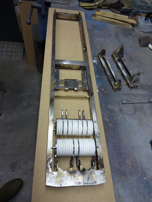
Parts pivot section S-boom
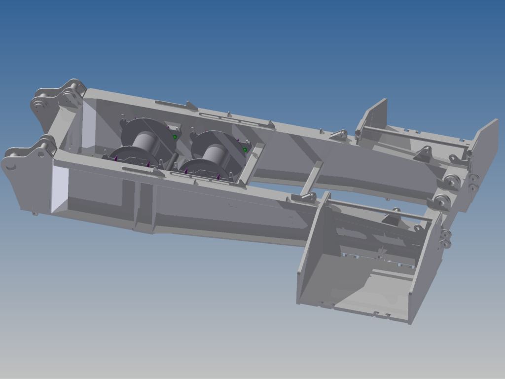
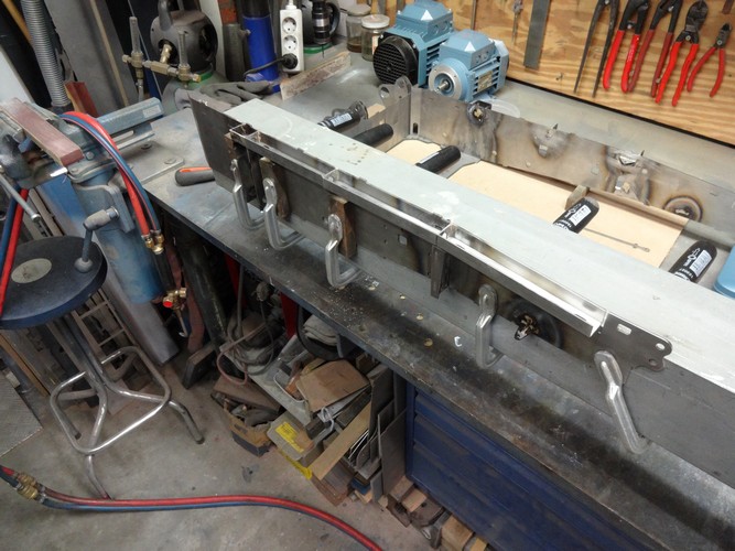
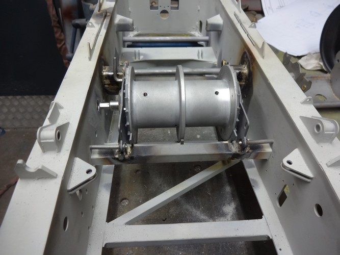
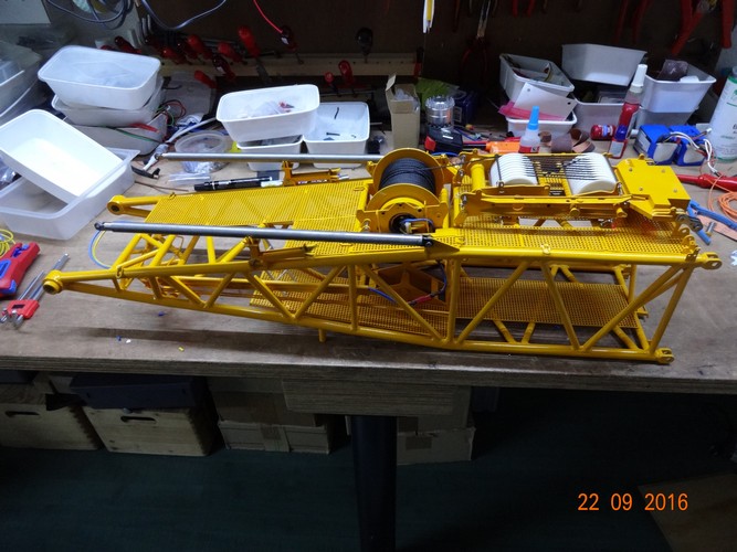
Reinforced deck for placing winches
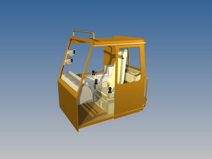
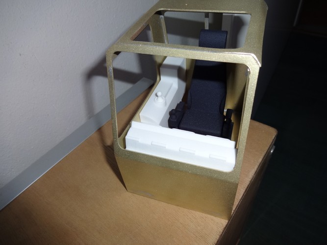
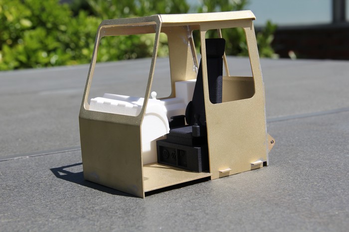
Cabin interior design
February 2015:
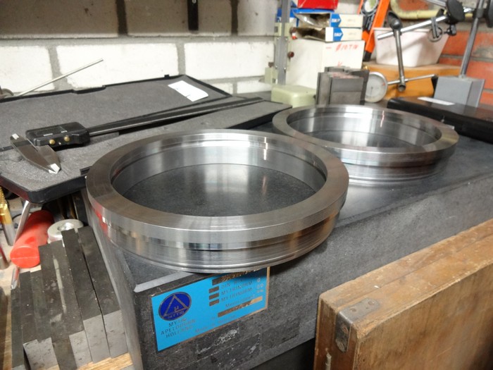
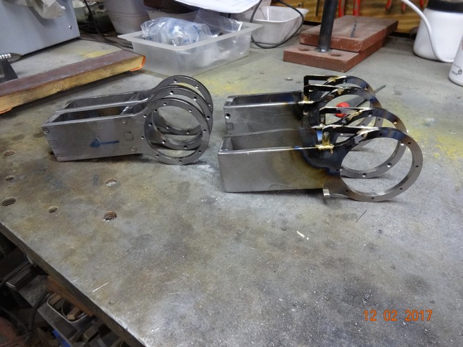
Made new base rings for the quick connector with fewer holes in the circumference
Blasting and painting the rings for the slewing rings
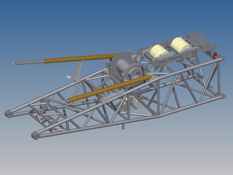
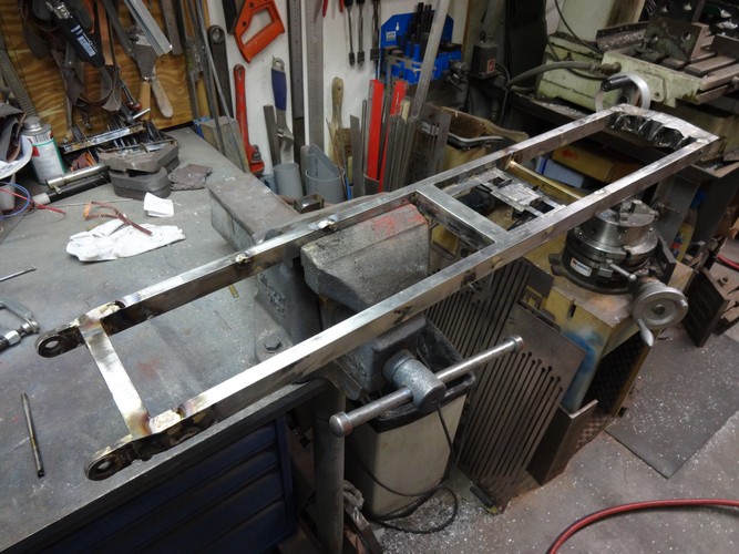
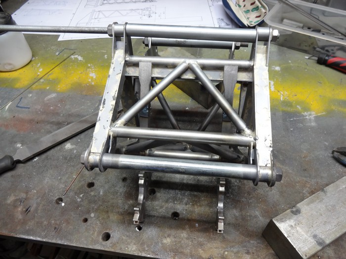
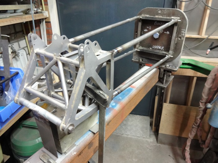
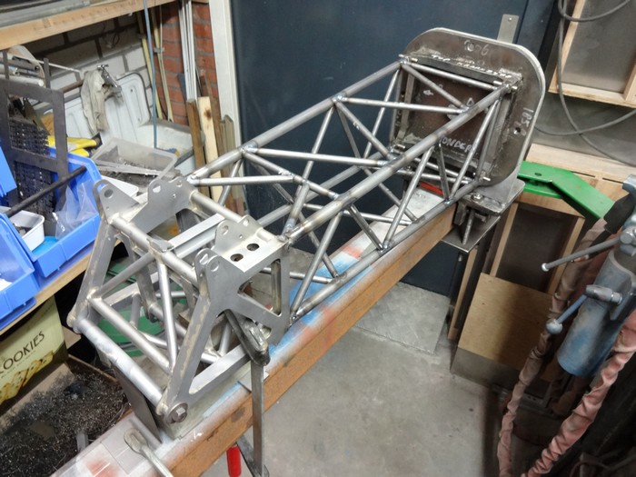
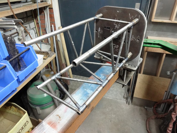
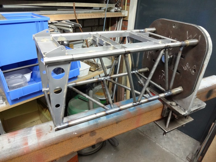
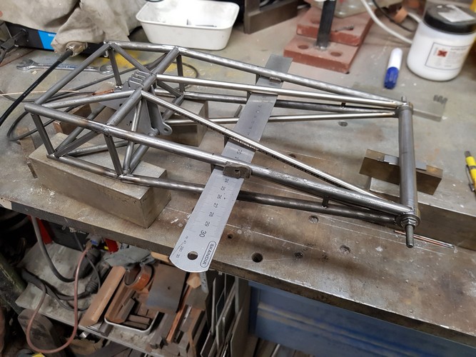
Assemble pivot section S-boom
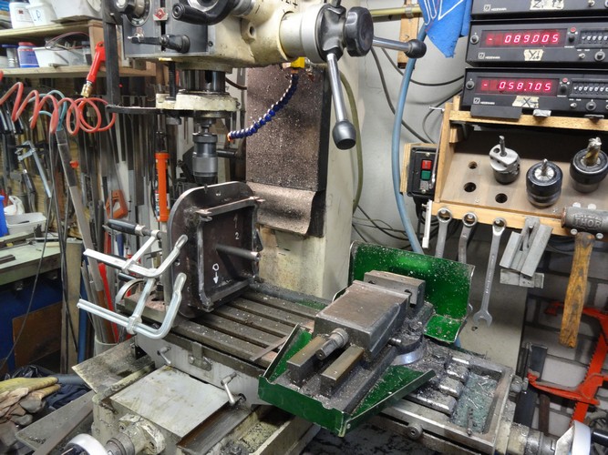
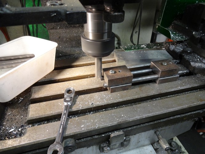
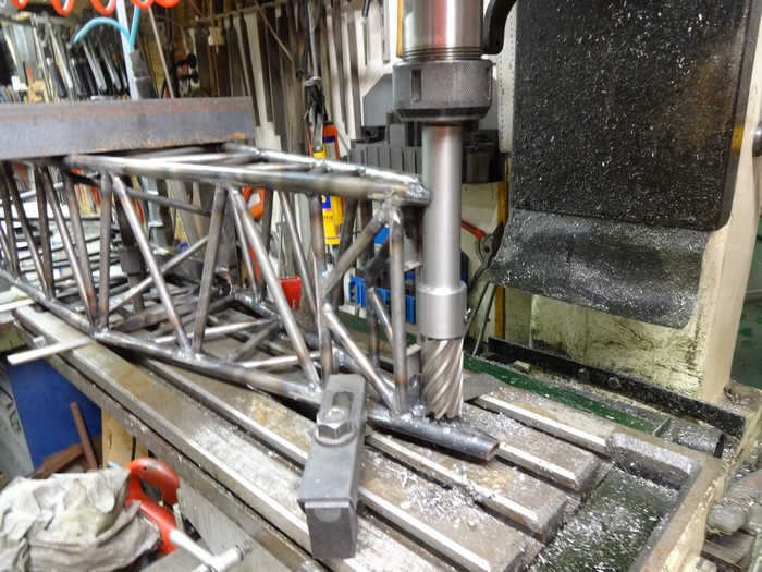
mill the main beams of the pivot section at the correct angle
Pre-composition tapered part of the pivot section
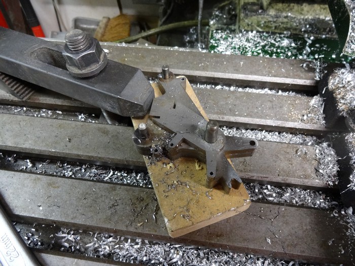
Mill the hinge point to the correct size
Special tool made to be able to mill the other sides from the same clamping
Weld couplings in a template
April 2015:
Check the perpendicularity of the boom in relation to the pivot points in the pivot section
Correcting the holes after welding the pivot points
Applying various details
Adjusting the winches
Application of various parts for the exhibition in Ede
Machining parts for the 600 ton sheave block
Sheave block mounted on Top-section S-boom
April 2015:
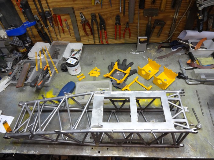
Assemble Central Ballast Plate
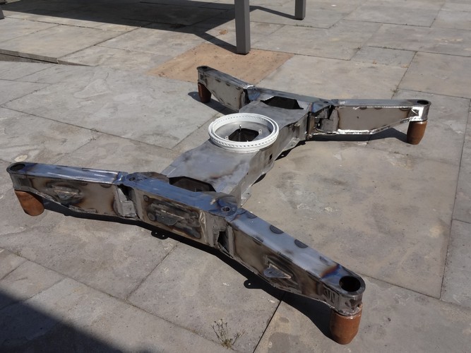
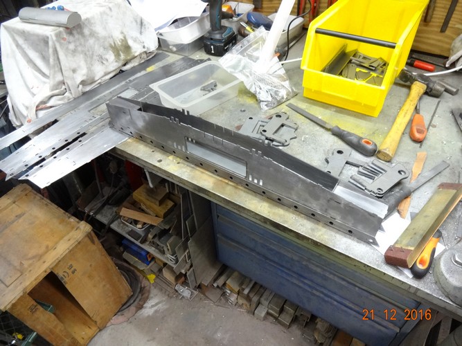
Started making parts for the Body
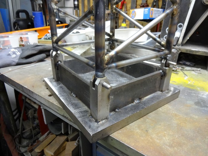
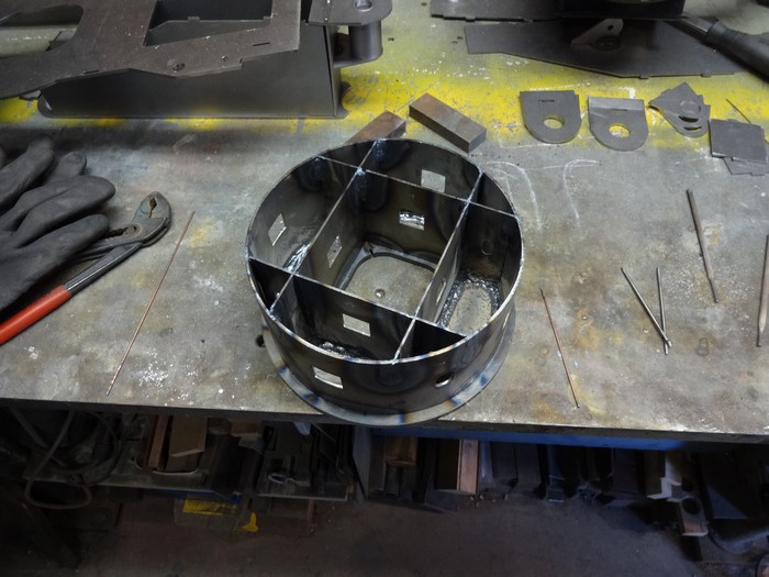
Assembling the foundation under the slewing ring
Welding parts of the slewing ring foundation
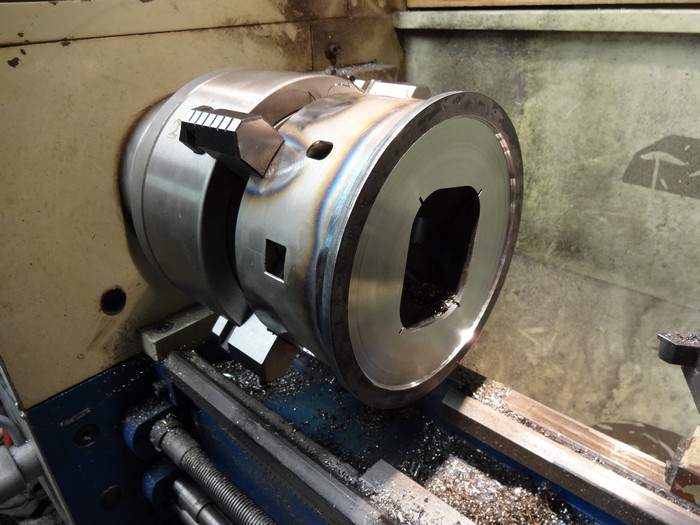
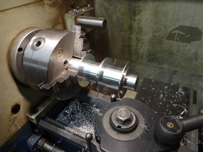
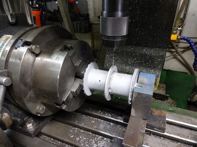
Turn the top of the foundation flat and in profile
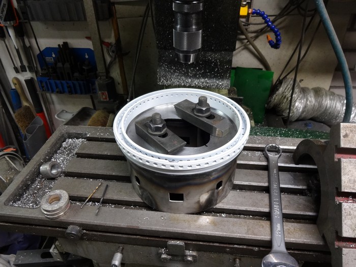
Drilling and tapping holes for quick connector base ring
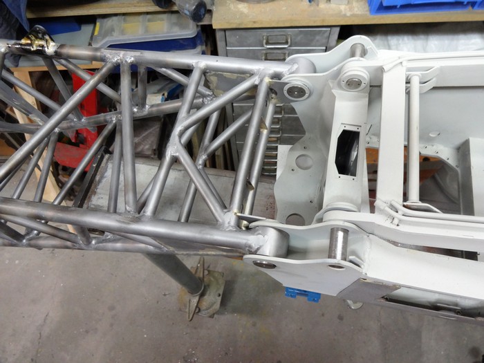
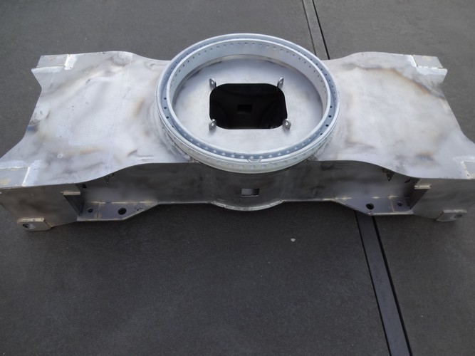
Continue with the assembly of the Body
Body with quick connector base-ring
May 2015:
Assembling the outriggers
June 2015:
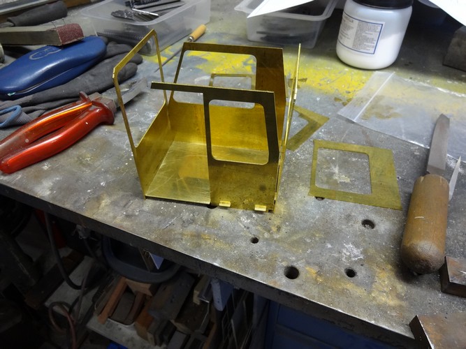
Assembling the Cabin
Parts of the interior 3D printed in plastic
Trial fit outriggers
July 2015:
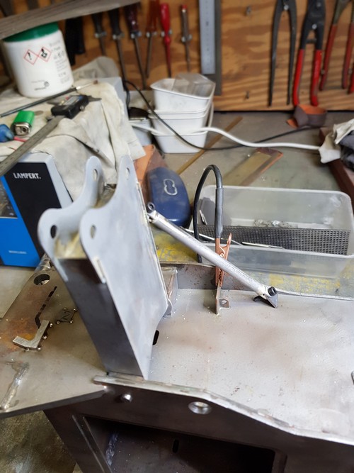
Design of the winch for the A-frame
October 2015:
Manufacturing winch A-frame
The winch is temporarily powered with a battery drill
November 2015:
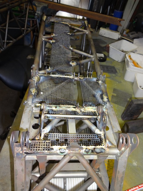
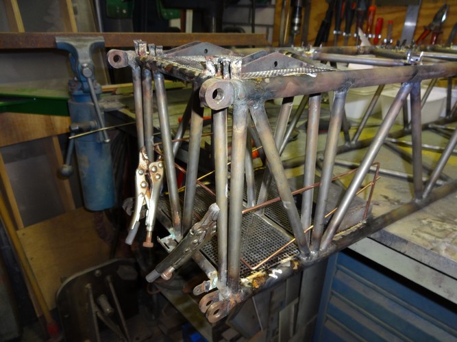
Applying details for tie rods and gratings on parts of the S-mast
Small details
Handrail
Removable handrail
December 2015:
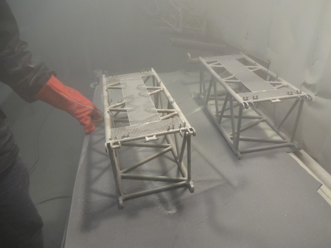
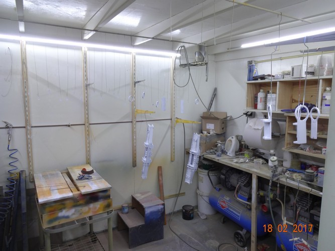
Sandblasting the boom sections and tie rods
Spraying the tie rods
Painting boom sections
January 2016:
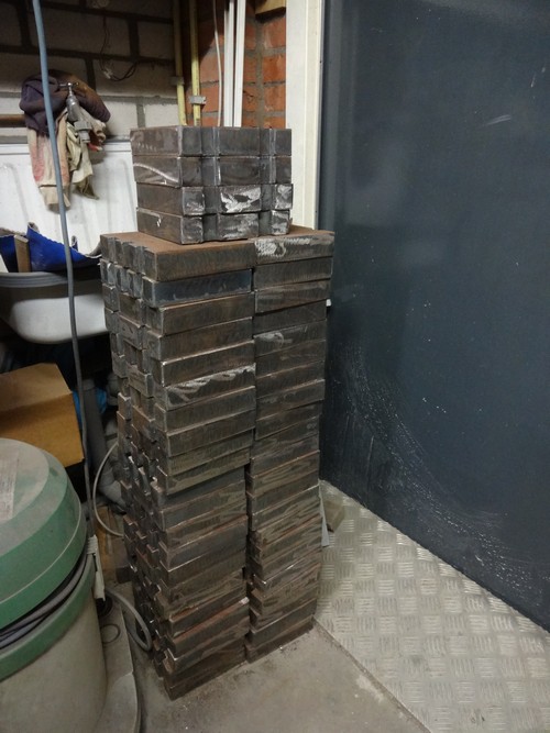
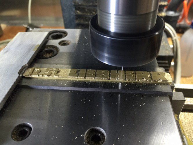
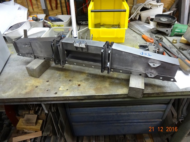
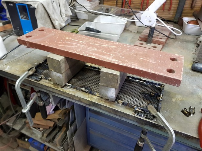
Autogenous cutting of 60 ballast blocks from 35 mm thick steel plate
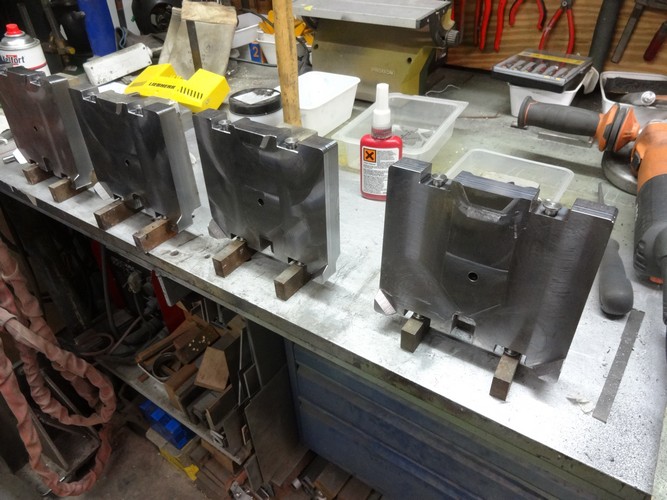
First machining
Machining ready
Applying trunions
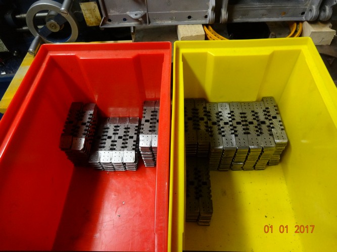
60 Ballast blocks before machining
60 Ballast blocks after machining
End result
February 2016:
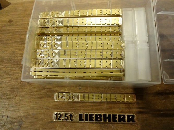
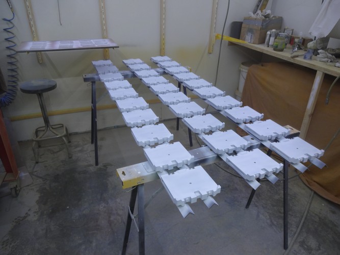
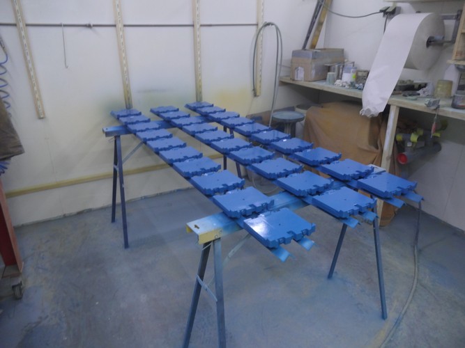
Spray the ballast blocks with primer
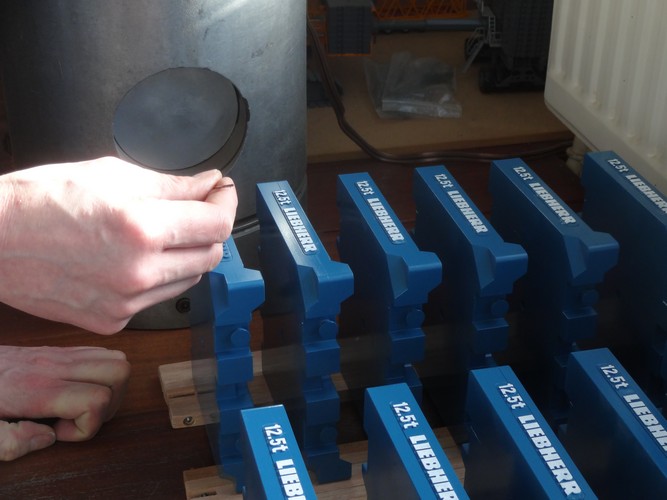
Paint letters white with mini roller
Assemble top of D-boom
Trial fit of Breidel to top D-boom
Template for assembling top-section D-boom
August 2016:
Make the layout for the ballast blocks in the cart
Special transport cart for all ballast blocks
Top-section D-boom
Side panel pivot section D-boom
Milling pivot point
Template for assembling the D-boom
September 2016:
Pivot section D-boom
Hydraulic straightening of boom sections after welding
Weld coupling pieces in the template
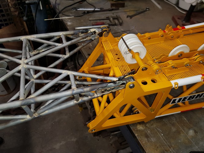
Trial fit D-boom
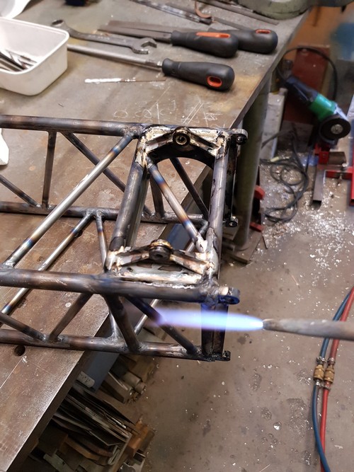
Applying details
Brazing the details
Reeving the Breidel according to drawing
Look for the differences
Look for the differences
Spray primer on the D-boom
Trial fit boom stoppers
October 2016:
Started with the 400 ton head section
Pre-assembly of the pivot point of the Jib pivot section
December 2016:
Painting the D-boom
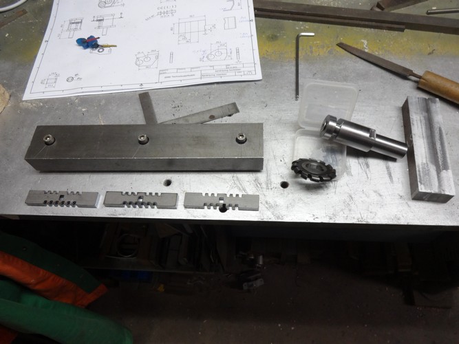
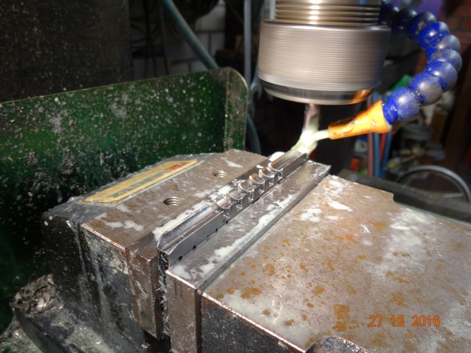
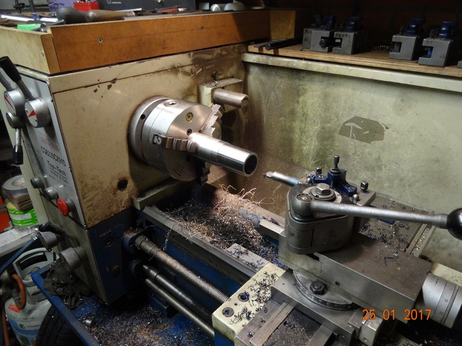
Manufacture clamping jig for machining track shoes
Groof milling to side track shoe attempt 1
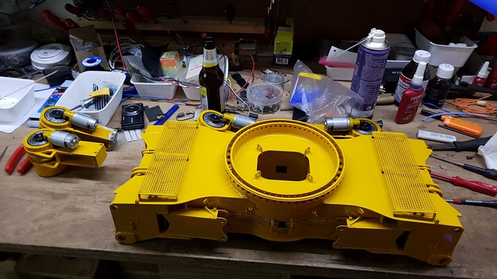
Assemble crawler carrier
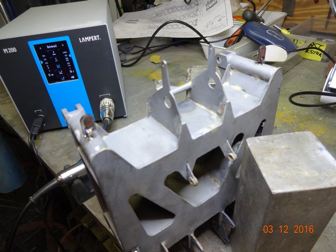
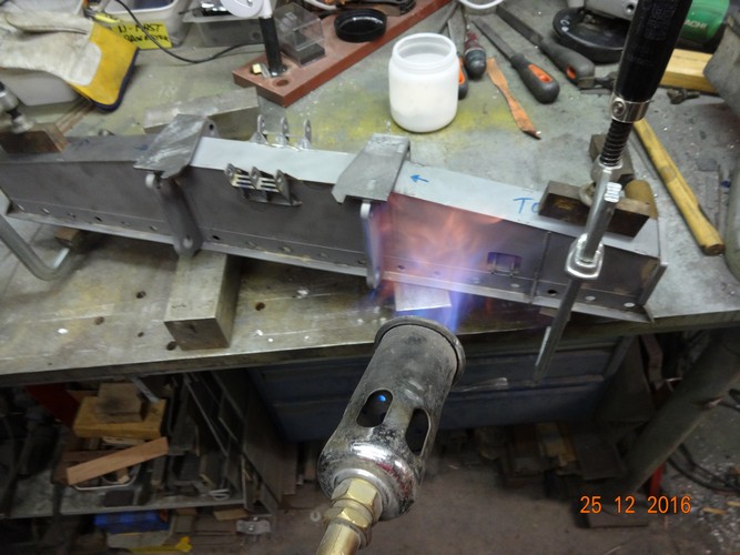
Pre-heating before brazing
Groof milling to side track shoe attempt 2
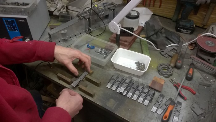
January 2017:
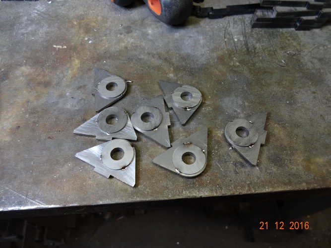
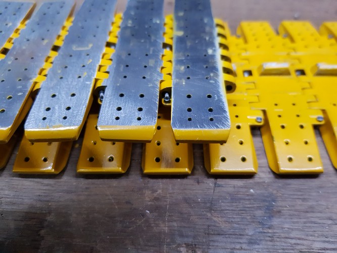
Machining track shoes
Spot welding track shoe parts together
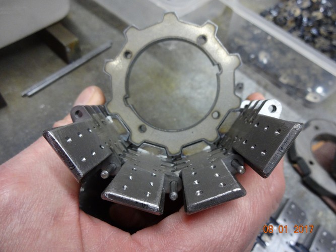
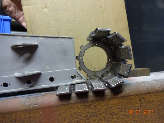
Trial fit track shoes around sprocket wheel
Real track shoe
Parts drive unit
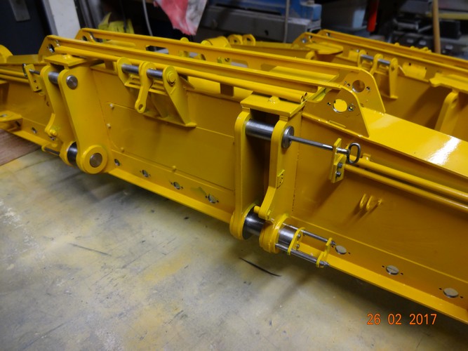
February 2017:
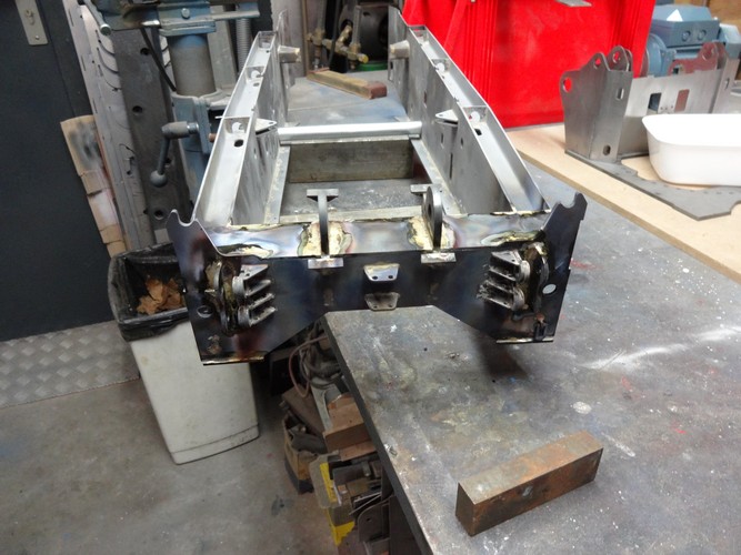
Crawler carrier
Parts drive unit
Fundation drive units
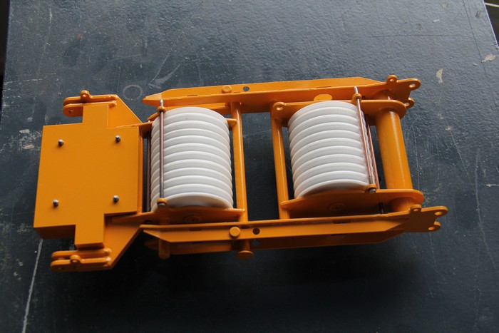
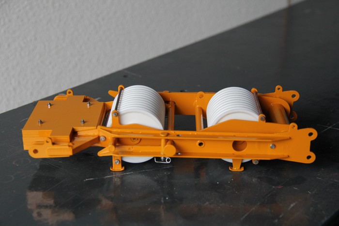
Painting the crawler carriers
Assemble drive units
Assemble crawler carrier
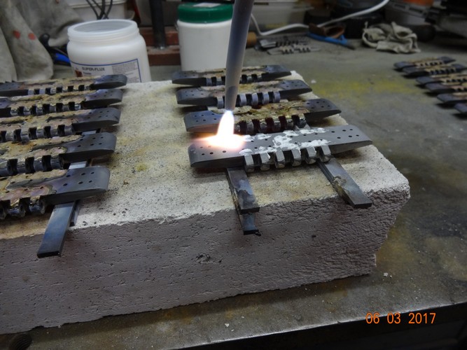
March 2017:
Brazing pivot points of the track shoes
Milling a chamfer at the cam of the shoe
Assemble sprocketwheel
Painting the track shoes
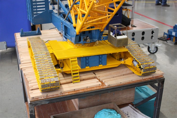
LR for the first time on tracks during Modelshow Europe in Ede
CNC milling work on the cover of the drive unit
October 2017:
Installing electronics
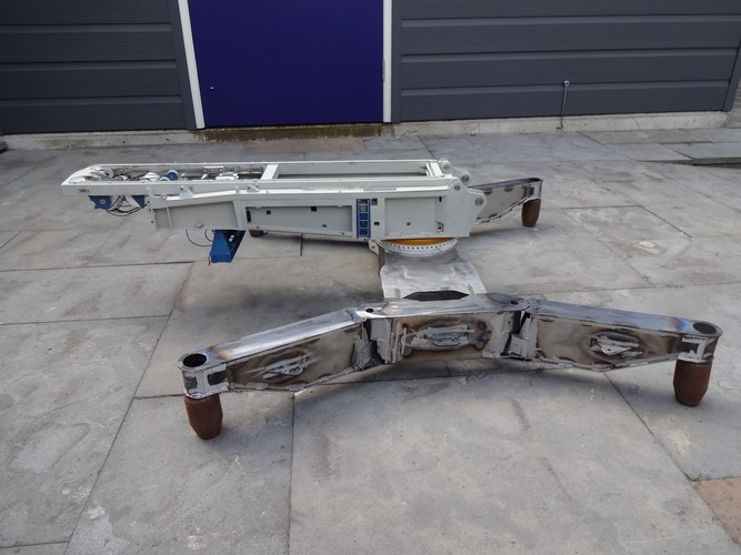
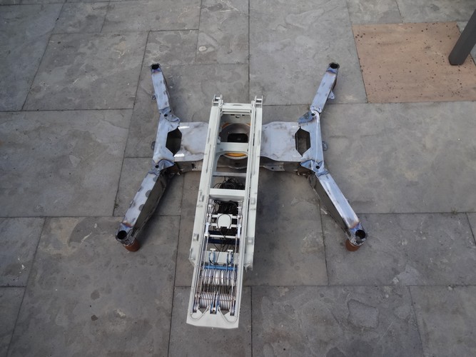
Outriggers carbody
Grating panel carbody
Marking of the pipework on the Carbody
Installing support legs
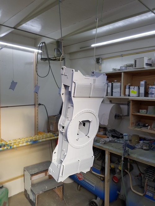
Applying primer layer
January 2018:
Ladder to grating platform
Overview grating platform carbody
Detail for pulling the pins
Assemble the tracks
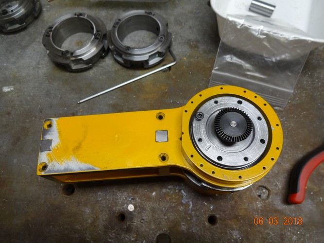
February 2018:
Parts drive unit
Lubricate the planetary gears for the drive units
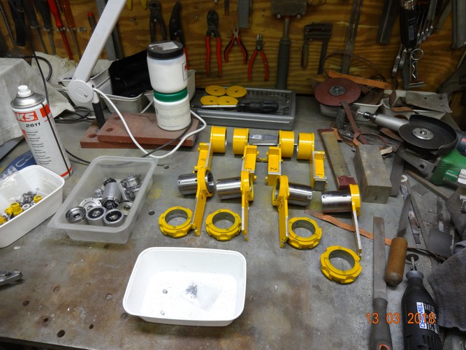
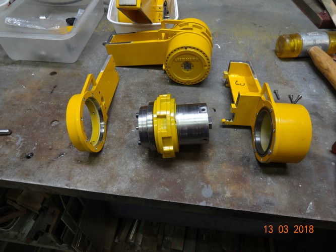
March 2018:
Assemble drive units
Electrically connecting the motors to the drive units
April 2018:
Test set-up in SL version
The result of 2 motors turning against each other
May 2018:
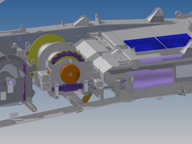
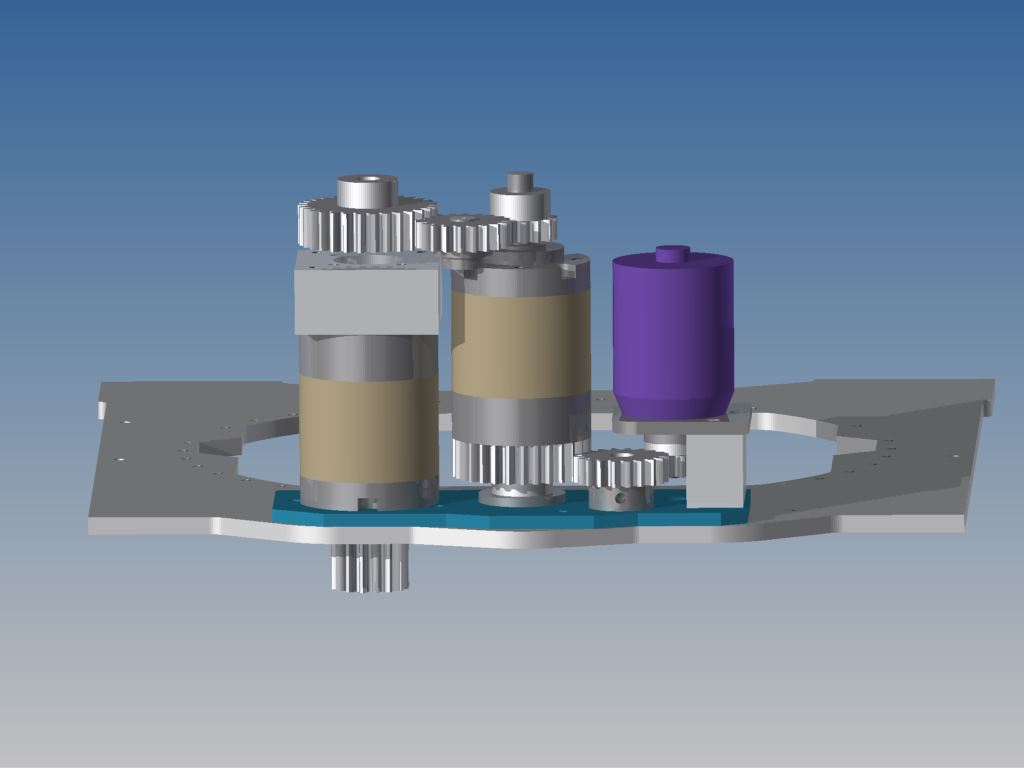
Design new slewing drive
Gear adjustment tool
June 2018:
Assemble side panel pivot section Jib
Construction of the pivot section Jib in welding template
Fly Jib LR 1750, details Top-section
Assemble side panel of the Top-section Jib
Construction of Top-section in welding template
Trial fit of 400 tons head section to Top-section
Brazing of the various parts
Maximum angle trial fit
Minimum angle trial fit
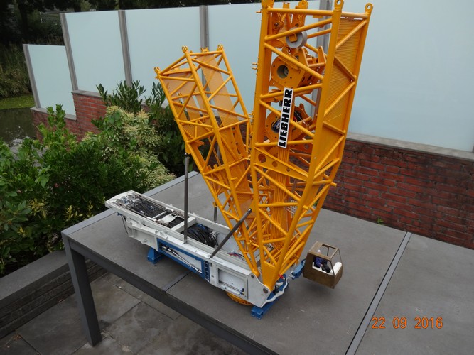
August 2018:
Assembling of Sprenkel W2
September 2018:
Assemble top of Sprenkel W2
Check height of section
Trial fit on 600 ton Top section S-boom
October 2018:
3D drawing Ballast tray
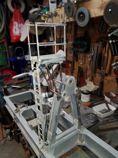
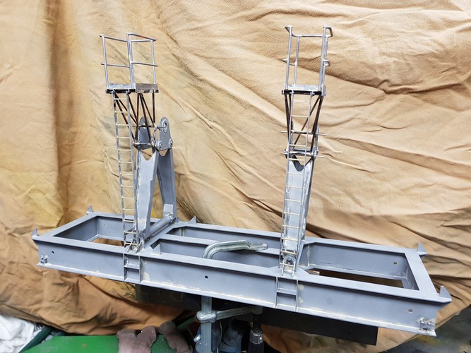
Assembling Sprenkel W1 pivot section
December 2018:
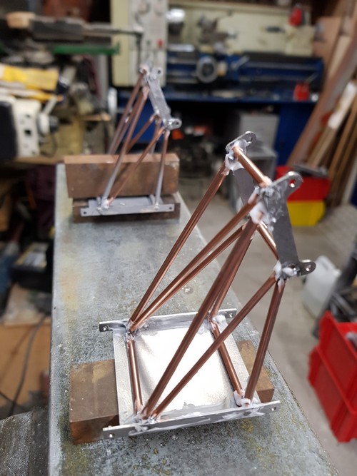
Assembling the Ballast tray
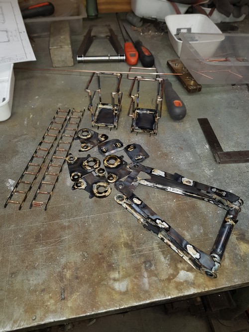
A-frames en bordessen voor de Ballasttray
A-frames and platforms for the Ballast Tray
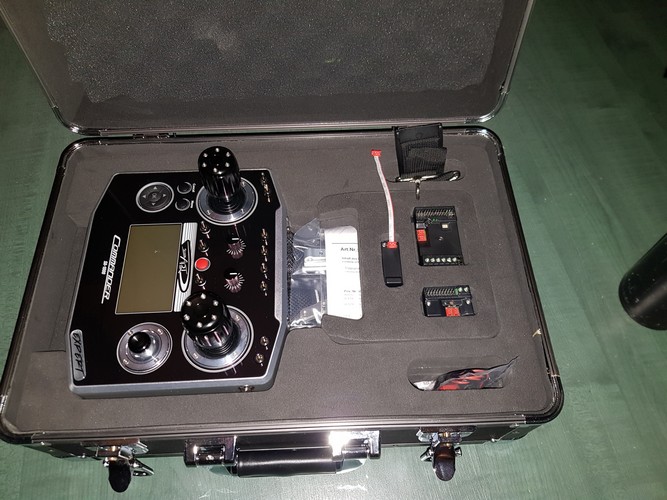
A new transmitter for the LR a Commander SA-1000 from ScaleArt,