In September of 1999, Marc and Richard started to make drawings of the LTM 1400. Initially, we planned to make one LTM together, but when it was time to start manufacturing the first parts, we decided to build one crane each, and have all the parts manufactured twice.
We decided that both of us should made drawings of a different part of the crane. When the drawings were completed they were joined together in a general arrangement to check for clashes with other parts. The construction was scheduled to take 3 years, because we both moved houses in the meantime and our workshops were dismantled for a while. We also have very busy jobs, and so the construction lasted a little longer.
Technical details:
Dimensions of the scale model
Dimensions of the real crane
Length of the crane
1400 mm
20300 mm
Width of the crane
206 mm
3000 mm
Height of the crane
275mm
4000mm
Length boom fully extended
3450mm
50000mm
Supporting base
690 x 690mm
10000 x 10000mm
Weight of the crane
75kg excl. ballast(geschat)
96 ton
Ballast
50kg
125 ton
Hydraulics working pressure
max. 50 bar
200 bar
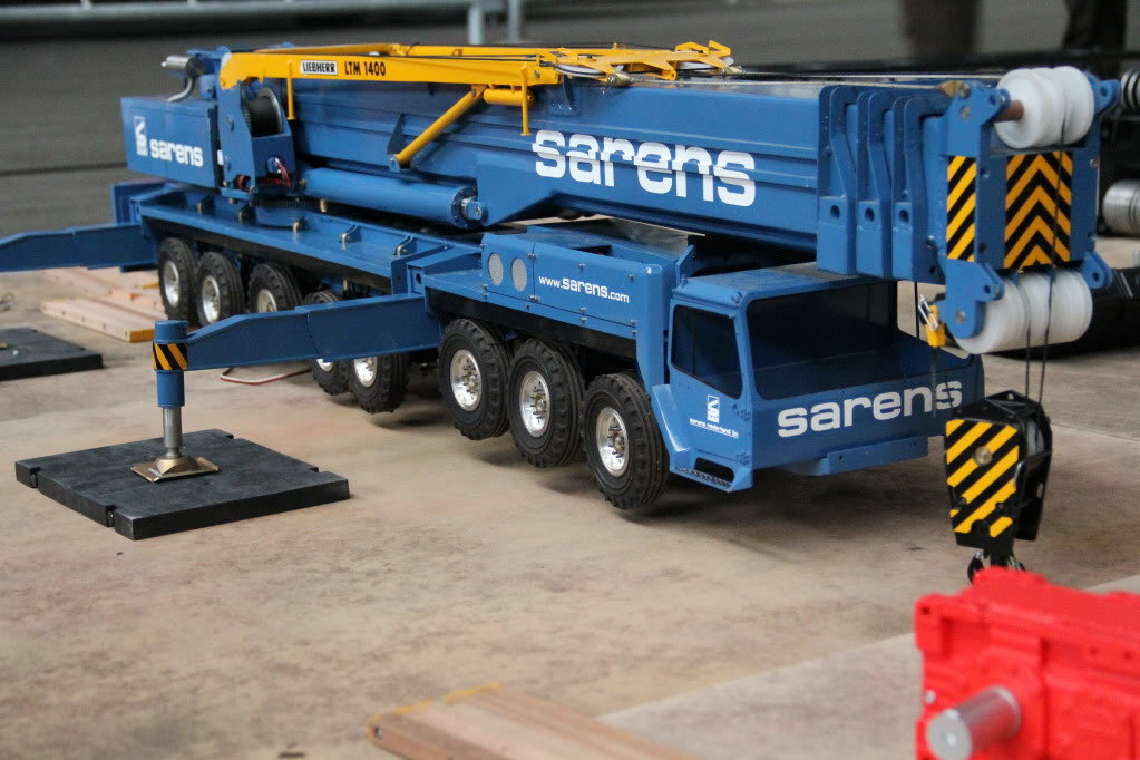
Axles 8 pieces 6 x steering wheels 2x rigid axles Powered axles 2 pcs The test lift was carried out with 41kg, using the 80 ton hook block fully reeved with 10 lines [41 kg/10 kg = 4.1 single line pull]. The 150-ton hoisting block is still under construction and in due course, this will also be tested [50 kg].
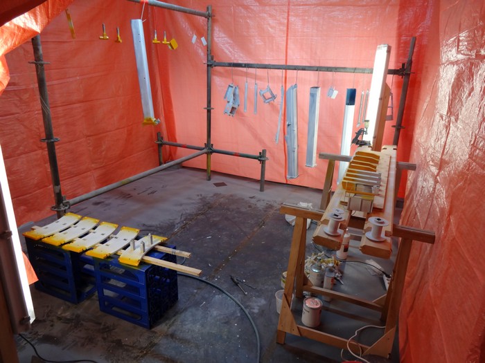
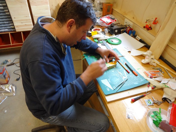
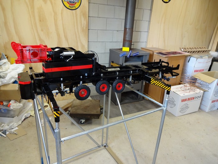
Pictures Liebherr LTM1400 during construction
Start September 1999
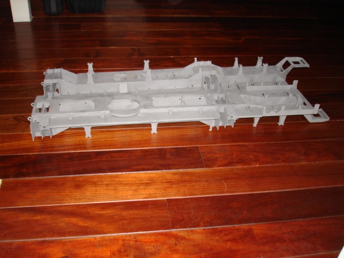
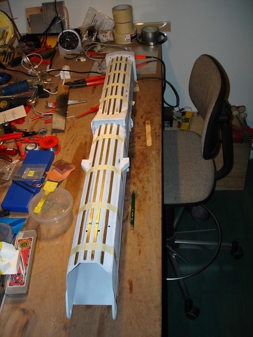
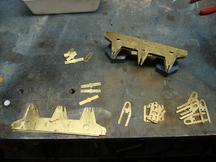
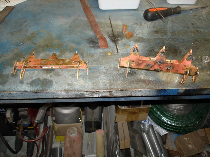
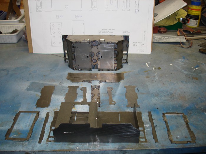
Mid-section chassis
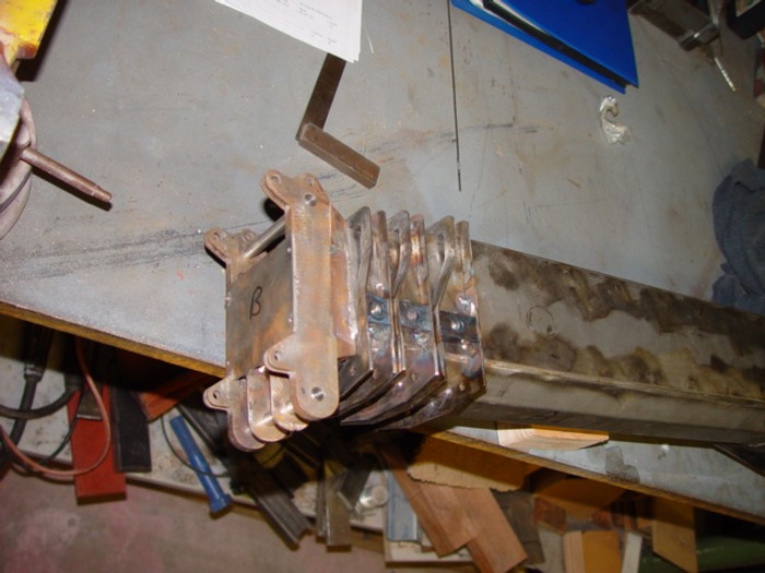
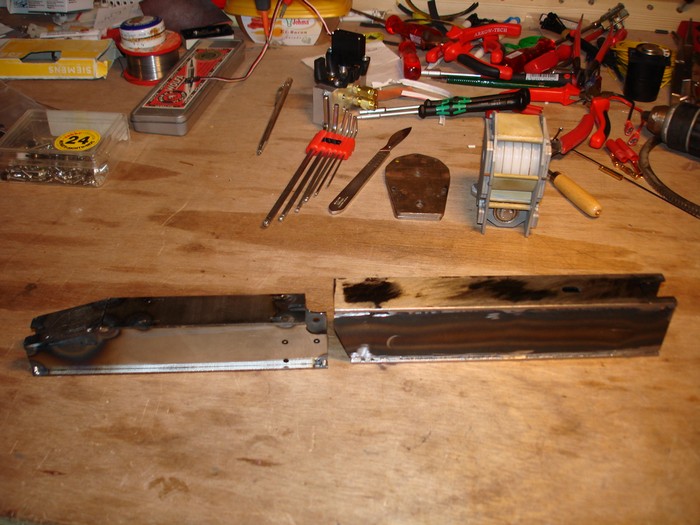
Chassis parts
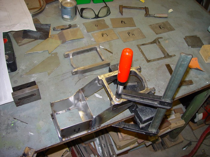
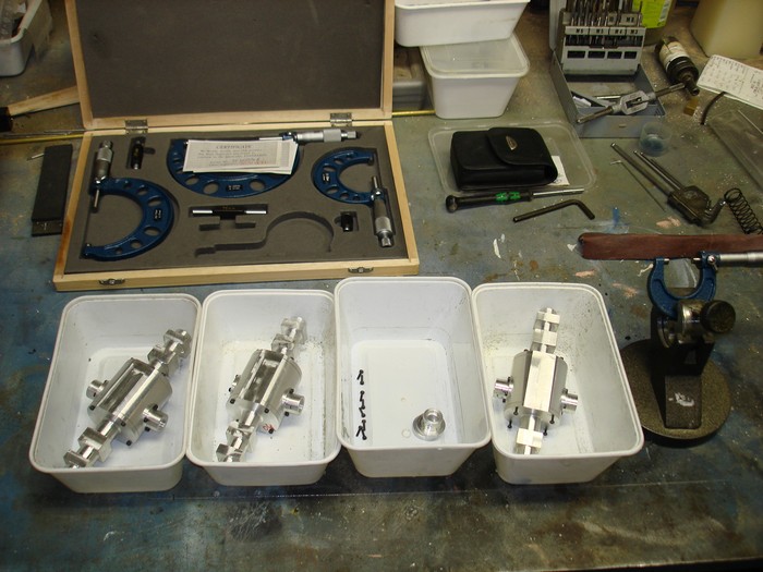
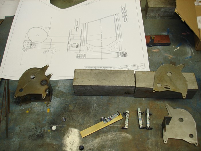
Trial fitting various parts
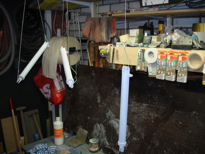
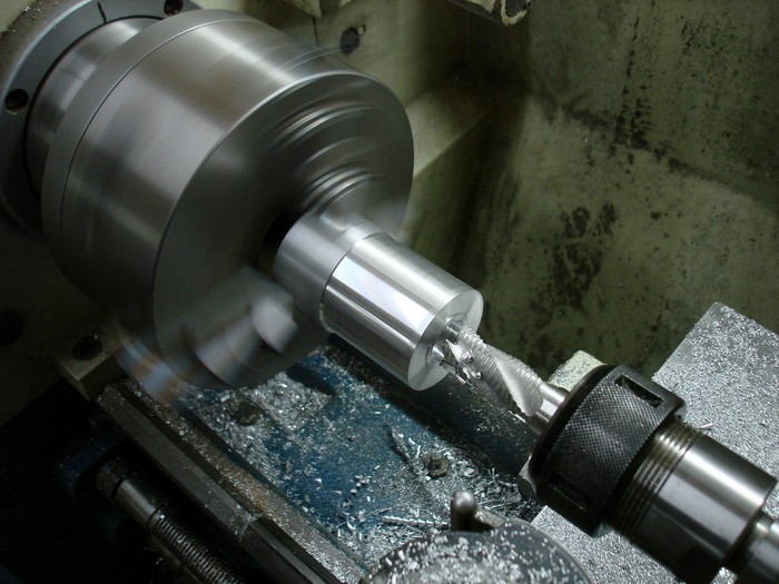
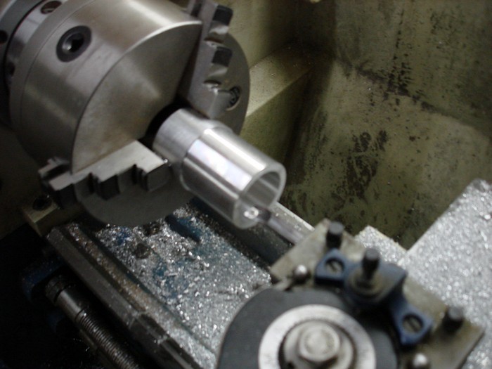
Polishing cylinder rods
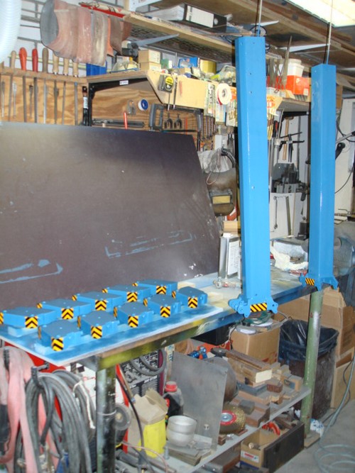
Assemble outriggers
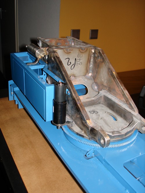
Assemble superstructure
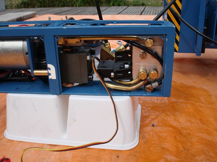
Engine compartment and hydraulic tank
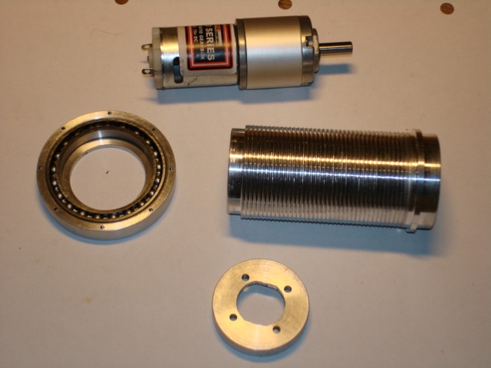
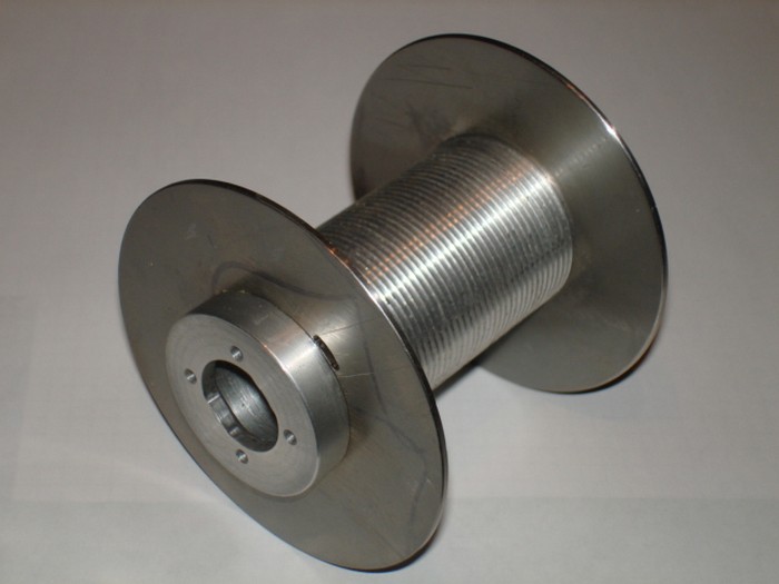
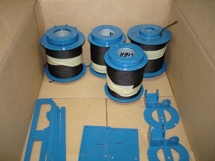
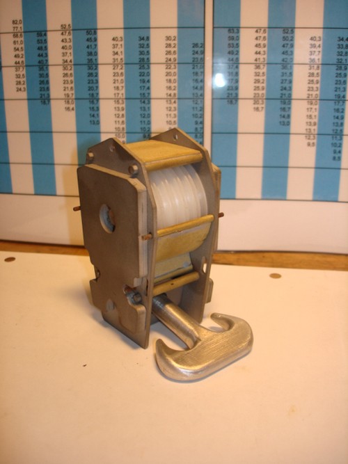
Winch drum in the lathe
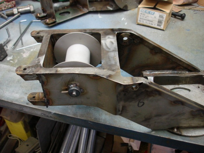
Winding 100mtr wire / winch
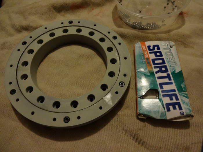
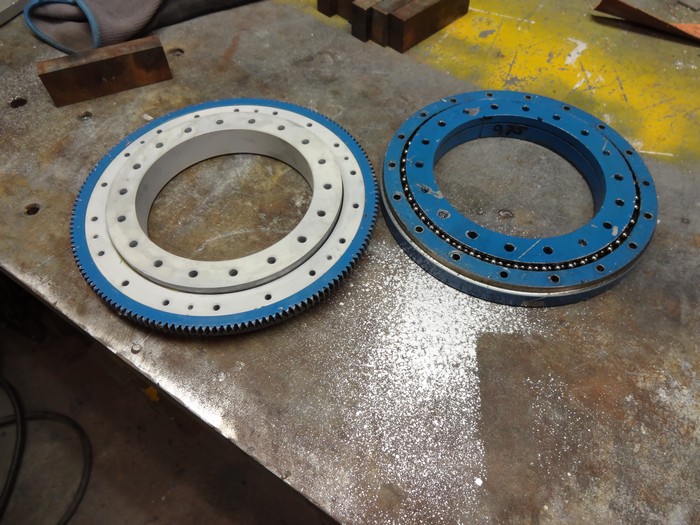
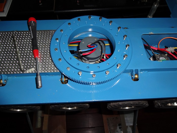
Parts slewing ring
Machining of the gearbox
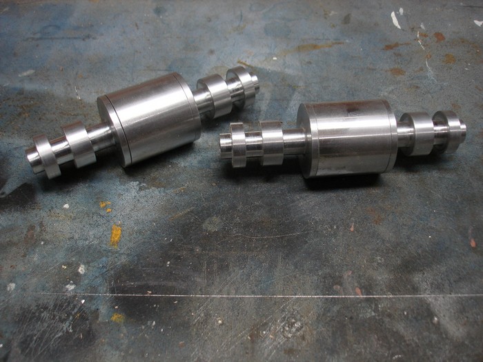
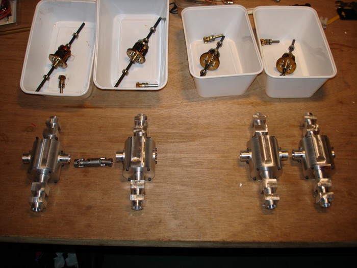
Various axles parts
Machining the differentials
assembling the differentials
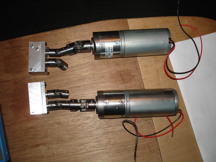
Hydraulics for the main cylinders
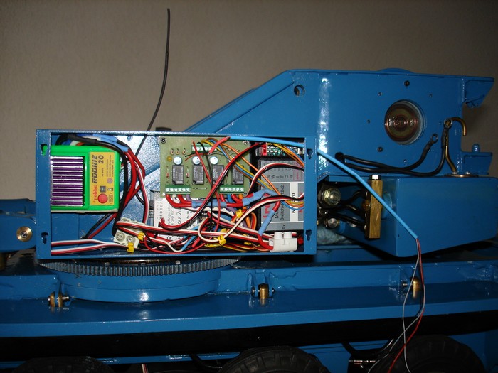
Installing electronics
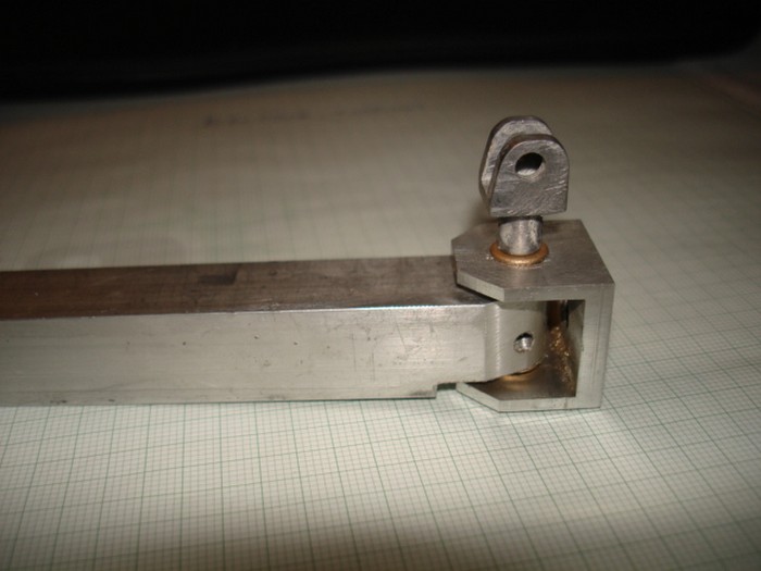
Assemble winch piece
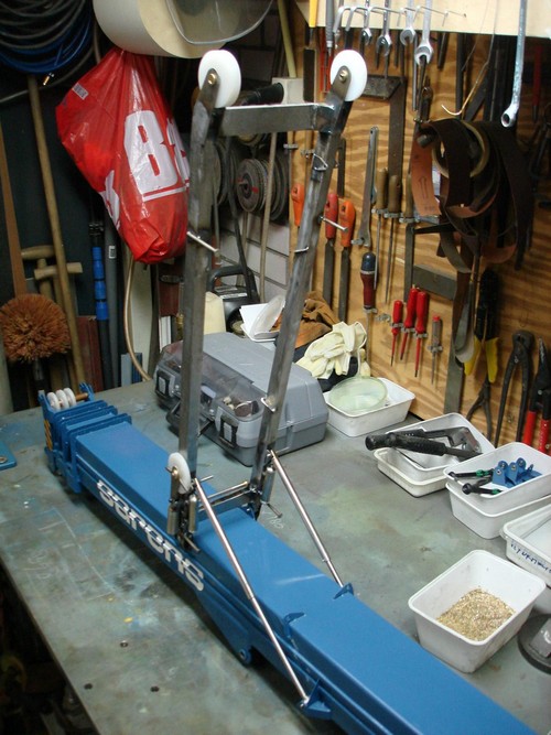
Assemble A-frame
Assemble pulley block
Trial fit
Assemble tension winch
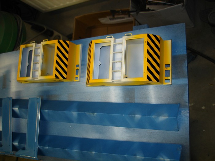
Assemble tool cabinet
80 tons hook
Engine compartment cover
Pulley block for fly Jib
Outrigger pads
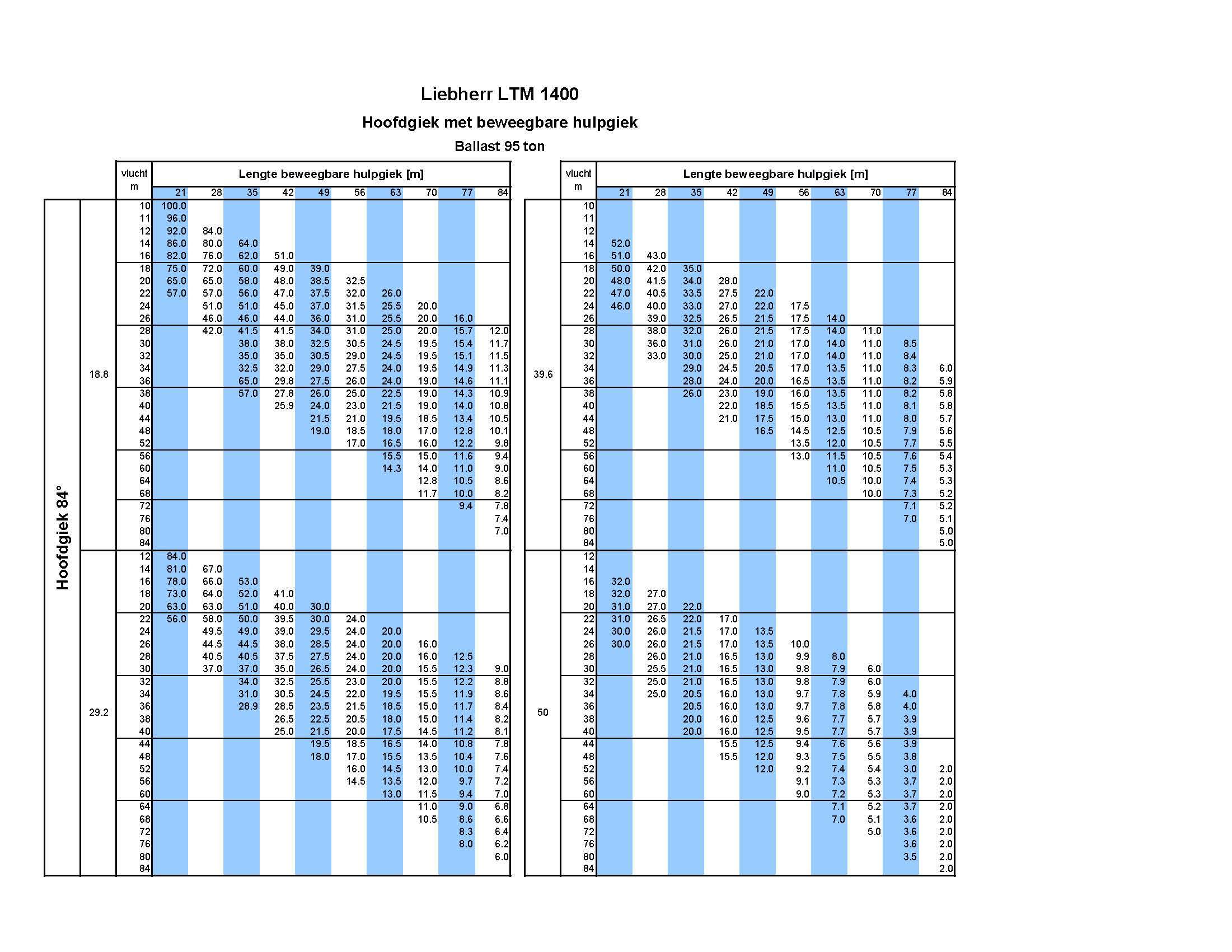
Main boom lifting table
Original table in tons
Scalemodel in kilograms
Lifting table with Fly jib
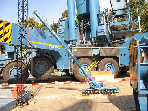
Loadtest with 42 kg at a radius of 70 cm
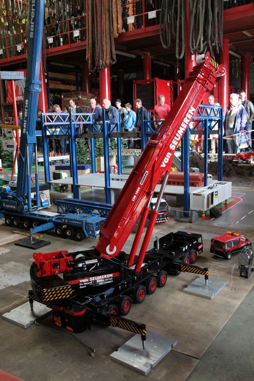
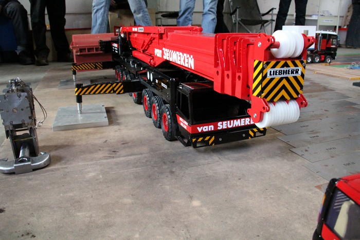
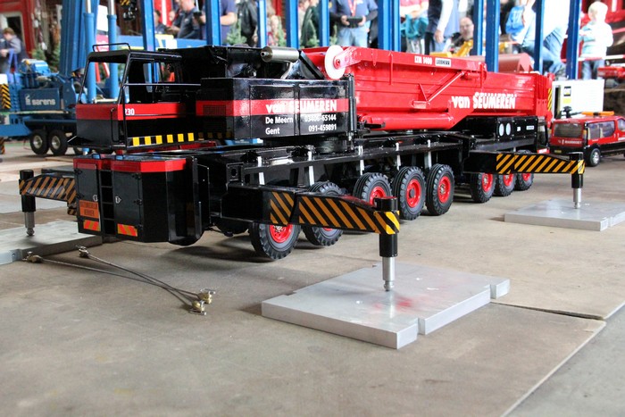
Marc's LTM gets a new color
Marc has decided to repaint his LTM1400 in the colors of the Van Seumeren company, so that it fits better with his other models. We managed to do this just before Mammoth Day in Schiedam.
Marc masking to be able to spray the stripping
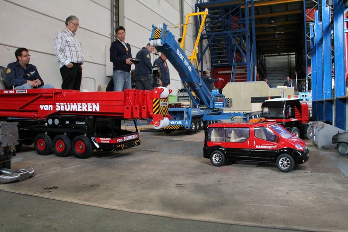
Shortly after the refinishing, the crane was on Mammoet Day
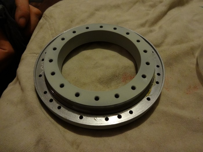
Revision of the slewing ring
In the beginning Marc made 2 designs for the slewing ring and in consultation we then decided together to make it like the real one with barrels in the bearing. Unfortunately, we later found out that the ratio of the diameter of the slewing ring to that of the barrels is not good, with the result that the bearing did not turn properly. In order to be able to use the bearing, we have replaced the barrels for balls, but because the running surfaces are at angles and there is too much space for the balls, they are in a W-shape in the bearing. As a result, the balls are regularly jammed against each other, which causes interference during the slewing. That is why we have taken the first design of Marc out of the box, a slewing ring with balls, only with a small adjustment which we tried out on the bearing of the LR 1750.
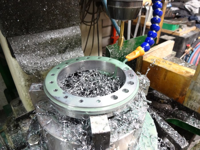
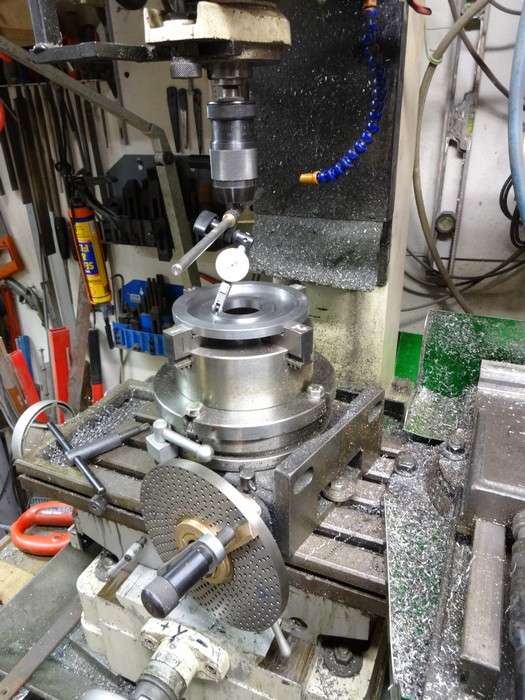
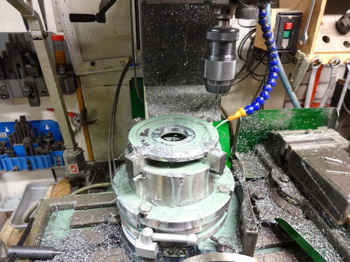
Pre-turning the rings for the slewing ring
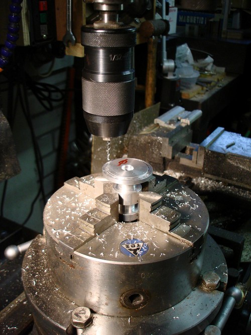
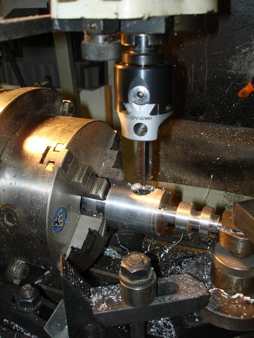
Drilling holes and making chambers
Making auxiliary tools for tension-free clamping of the rings